
Breeze L4-2.4L VIN X (2000)
4. Install the 25-way connector into the socket on the CAB. The connector is installed using the following procedure. Position the 25-way connector
in the socket on the CAB and carefully push it down as far as it will go. When connector is fully seated into the CAB socket push in the connector
lock as far as it will go. This will pull the 26-way connector into the socket on the CAB and lock it in the installed position.
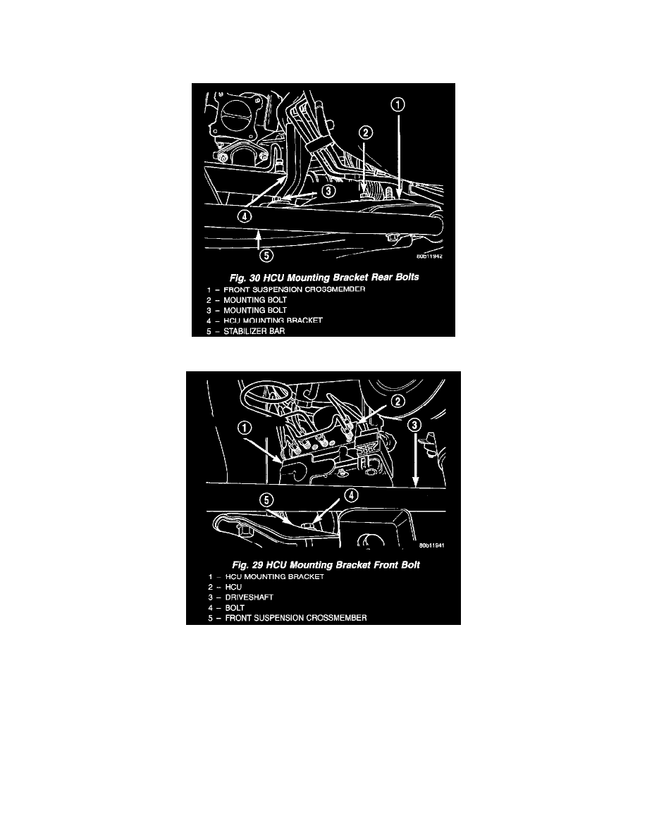
5. Install the 2 bolts attaching the back legs of the HCU mounting bracket to the front suspension crossmember.
6. Install the bolt attaching the front leg of the HCU mounting bracket to the front suspension crossmember.
7. Tighten the 3 bolts mounting the HCU mounting to the front suspension crossmember to a torque of 28 Nm (250 inch lbs.).