
Breeze L4-2.4L VIN X (2000)
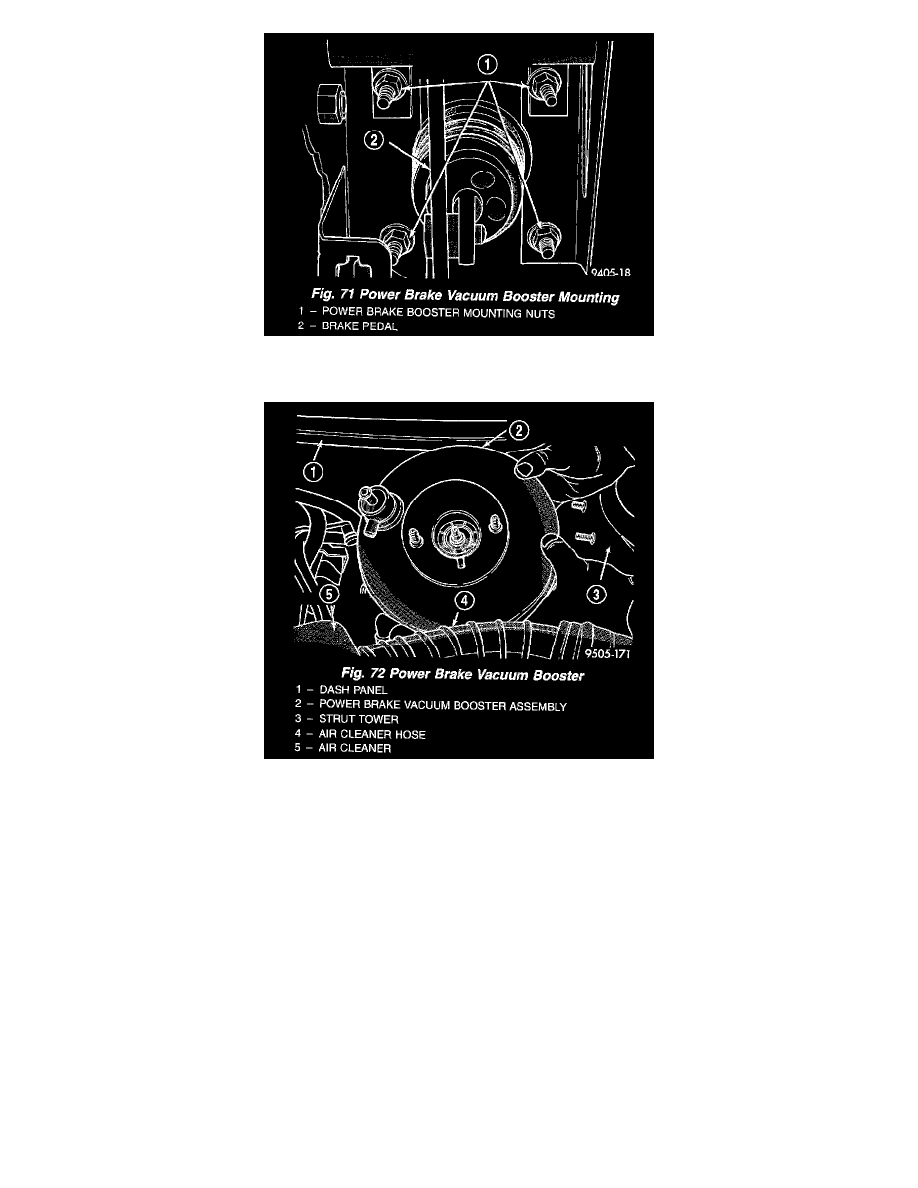
11. Remove the 4 nuts attaching power brake vacuum booster to dash panel. Nuts are accessible from under dash panel in area of the steering column
and pedal bracket assembly.
12. Slide power brake vacuum booster forward until mounting studs clear dash panel and then tilt up and rotate toward center of vehicle to remove.
CAUTION: Do not attempt to disassemble the power brake vacuum booster it is to be serviced ONLY as a complete assembly.
INSTALLATION
1. Position power brake booster onto dash panel.
2. Install and torque the 4 power brake vacuum booster mounting nuts to 29 Nm (250 inch lbs.) torque.
3. Using lubriplate, or an equivalent, coat the surfaces of the brake pedal pin that contact the power brake vacuum booster input rod.
4. Connect power brake vacuum booster input rod to brake pedal pin and install a NEW retaining clip.
Use only a new retainer clip DO NOT USE the old clip.
5. Position master cylinder on studs of power brake unit, aligning push rod on power brake vacuum booster with master cylinder push rod.
6. Install the 2 master cylinder to power brake unit mounting nuts. Tighten the 2 mounting nuts to a torque of 28 Nm (250 inch lbs.).
7. Install the vehicle's wiring harness connector on the master cylinder brake fluid level sensor.
8. Install the purge control solenoid on the left front frame rail. Tighten the purge control solenoid mounting bolt.
9. Install the EGR transducer assembly on the EGR valve. Install the vehicle wiring harness connector on the EGR transducer, ensuring the retaining
clip is fully engaged with transducer.
10. Connect all previously removed vacuum hoses onto the power brake vacuum booster check valve.
11. If equipped, install speed control servo on the mounting studs in the left strut tower. Install the 2 speed control servo bracket mounting nuts.
Tighten the 2 mounting nuts to a torque of 6 Nm (55 inch lbs.).
12. Check brake light switch for correct adjustment. If required, adjust stop lamp switch as necessary. See required procedure found at Lighting and
Horns, Brake Light Switch, Adjustment.
13. Road test vehicle to ensure proper operation of the vehicles brake system.