
Breeze L4-2.4L VIN X (2000)
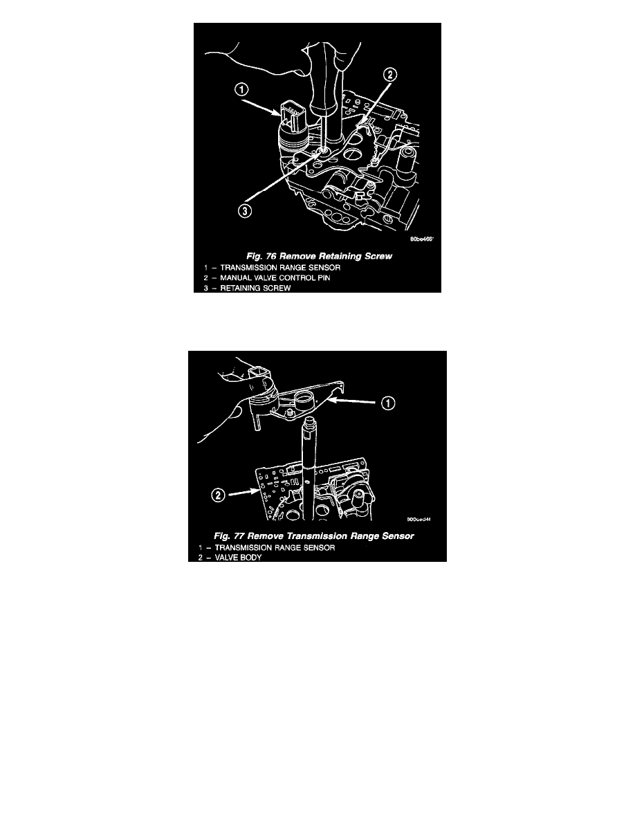
Fig. 76
13. Remove TRS retaining screw (Fig. 76).
Fig. 77
14. Slide Transmission Range Sensor up the manual shaft and remove (Fig. 77).
INSTALLATION
1. Install transmission range sensor (Fig. 77).
2. Tighten retaining screw (Fig. 76) to 5 Nm (45 inch lbs.).
3. Install manual shaft seal (Fig. 75).
4. Guide park rod rollers into guide bracket while installing valve body to the transaxle case (Fig. 73) (Fig. 74).
5. Install the valve body-to-case bolts (Fig. 72) and torque to 12 Nm (105 inch lbs.).
6. Install the oil filter (Fig. 71). Inspect the O-ring for damage and replace as necessary.
7. Install an 1/8" bead of RTV as shown in (Fig. 70) and install pan to case.
8. Install oil pan bolts (Fig. 69) and torque to 19 Nm (165 inch lbs.) torque.
9. Lower vehicle.
10. Connect transmission range sensor connector.
11. Install manual valve lever to manual valve.
12. Install gear shift cable to manual valve lever (Fig. 68).
13. Install air cleaner assembly.
14. Connect battery negative cable.