
Breeze L4-2.4L VIN X (2000)
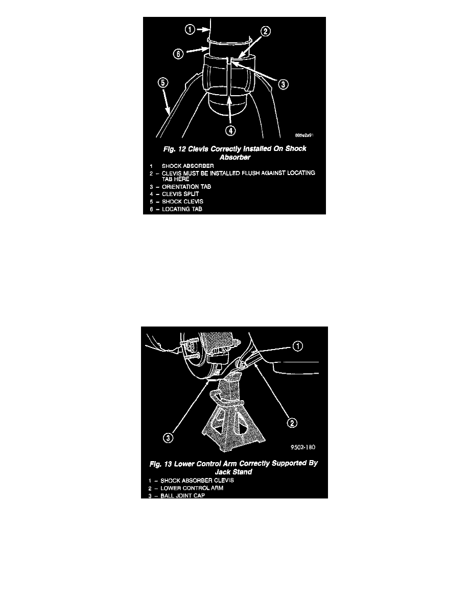
Fig. 12
2. Install the clevis bracket on the shock absorber. Clevis is installed by tapping it onto the fluid reservoir of the shock absorber using a soft (brass)
drift until fully seated against locating tab on shock absorber. The orientation tab on the shock absorber locating tab must be positioned in the split
of the clevis.
3. Install the clevis to shock absorber pinch bolt. Do not tighten or torque the bolt at this time.
4. Install the clevis bracket to lower control arm thru-bolt. Do not tighten or torque the thrubolt at this time.
5. Tighten the clevis to shock absorber pinch bolt to a torque of 70 Nm (52 ft. lbs.).
6. Install upper ball joint into steering knuckle. Install castle nut on ball joint stud. Tighten castle nut to a torque of 62 Nm (45 ft. lbs.). Install cotter
pin in stud of ball joint.
7. Install the routing bracket for the speed control cable on the steering knuckle. Install and securely tighten the routing bracket attaching bolt.
Fig. 13
CAUTION: When supporting lower control arm with jack stand, do not position jack stand under the ball joint cap on the lower control arm.
Position in area of lower control arm shown in.
8. Lower vehicle to the ground with a jack stand positioned under the lower control arm. Continue to lower vehicle so the total weight of the vehicle
is supported by the jack stand and lower control arm.
9. Tighten the shock absorber clevis to lower control arm bushing thru-bolt to a torque of 90 Nm (68 ft. lbs.).
10. Raise the vehicle, then remove the jack stand.