
Colt L4-1597cc 1.6L DOHC (1990)
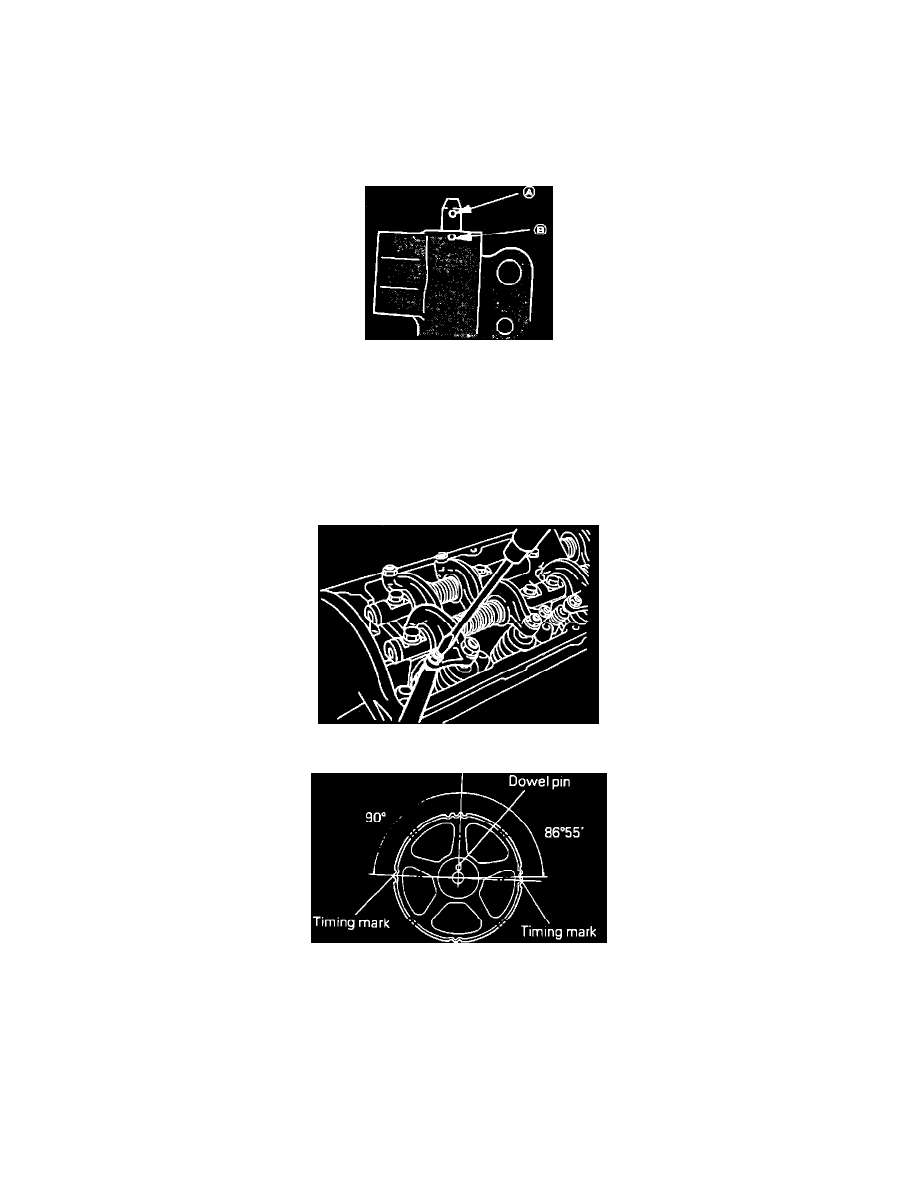
Fig. 17 Installing Crankshaft Sprocket And Flange
INSTALLATION
1.
Install spacer, flange and crankshaft sprocket. Ensure crankshaft sprocket and flange are correctly installed as shown in Fig. 17.
2.
Install oil pump sprocket, torquing attaching nut to specifications.
3.
Install camshaft sprockets. Using a wrench, hold the camshaft at the hexagonal portion (between No. 2 and No. 3 journals) and tighten attaching
bolt. Locking the camshaft sprocket with a tool may damage the sprocket.
Fig. 18 Aligning Auto Tensional Rod
4.
Install auto tensioner. If tensioner rod is fully extended, proceed as follows:
a. Position auto tensioner level in a soft jawed vise. If plug at bottom of tensioner protrudes, apply a plain washer to prevent the plug from direct
contact with vise.
b. Slowly push tensioner rod in, using the vise, until set hole (A) is aligned with hole (B) in the tensioner cylinder, Fig. 18.
c. Insert a wire .055 inch (1.4 mm) in diameter into the set holes, then remove auto tensioner from the vise.
d. Install auto tensioner. Leave the wire installed in the auto tensioner.
5.
Install tensioner pulley onto tensioner arm, position the hole in pulley shaft to the left of the center bolt, then tighten center bolt finger tight.
Fig. 6 Adjusting Jet Valve Clearance
Fig. 19 Positioning Camshaft Sprocket Timing Marks
6.
Rotate camshaft sprockets so that their dowel pins are located on top, then align the timing marks facing each other with the top surface of cylinder
head, Fig. 6. When exhaust camshaft is released, it will rotate one tooth in the counterclockwise direction. This should be taken into account when
installing timing belt on sprockets. The camshaft sprockets are interchangeable and have two sets of timing marks. When the sprocket is
mounted on the exhaust camshaft, use the timing mark on the right with dowel pin hole on top. For the intake sprocket, use the mark on
the left with dowel pin hole on top, Fig. 19.
7.
Align camshaft sprocket and oil pump sprocket timing marks as shown, Fig. 5.