
Colt L4-1597cc 1.6L DOHC (1990)
Inhibitor Switch: Testing and Inspection
NOTE: Verify that the Control Cable is not damaged and is properly adjusted, prior to performing this test. Refer to ADJUSTMENT PROCEDURES.
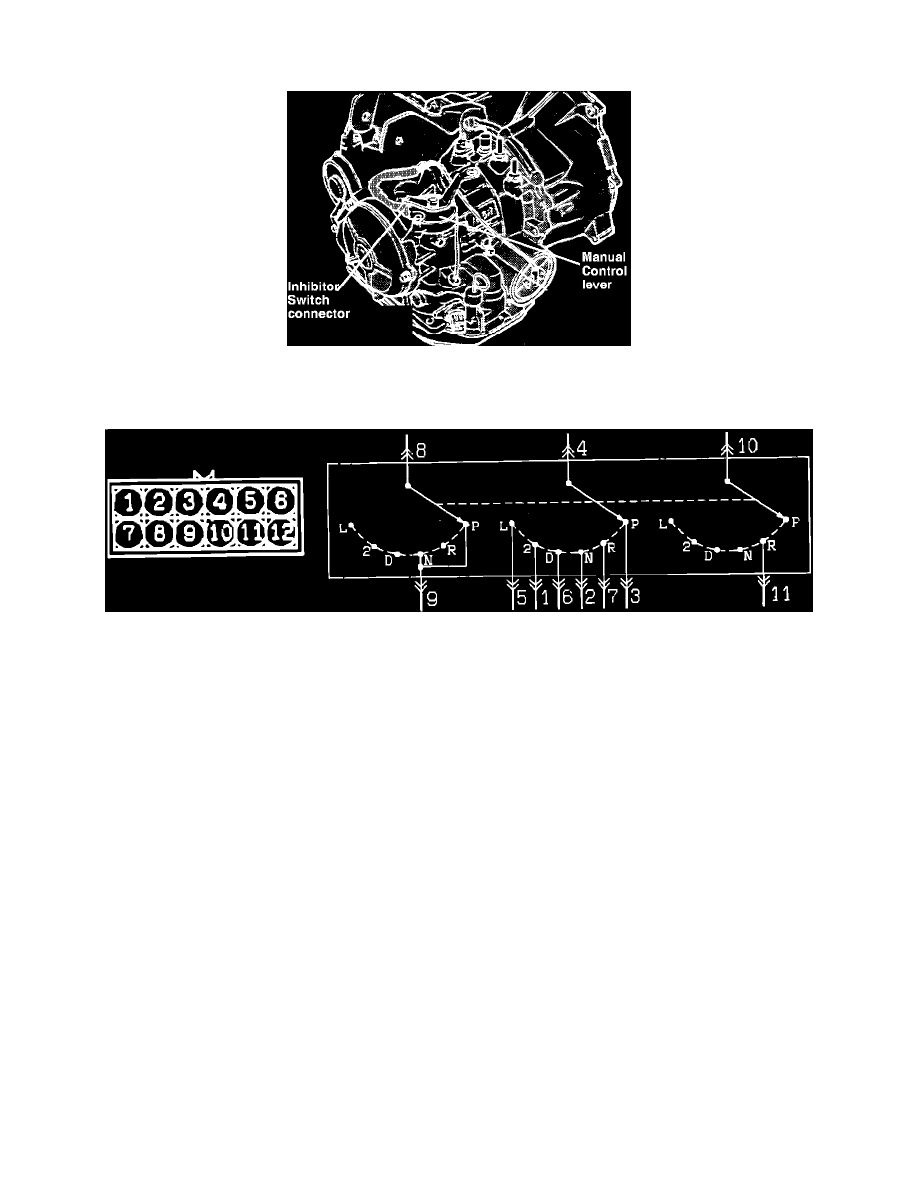
Inhibitor Switch Connector
1.
Disconnect the Inhibitor Switch electrical connector.
Inhibitor Switch Connections
2.
With the gear selector in Park, check for continuity between terminals # 3 and # 4, and between terminals # 8 and # 9.
Continuity should exist.
3.
Shift the gear selector to REVERSE, check for continuity between terminals # 4 and # 7, and between terminals # 10 and # 11.
Continuity should exist.
4.
Shift the gear selector to NEUTRAL, check for continuity between terminals # 2 and # 4, and between terminals # 8 and # 9.
Continuity should exist.
5.
Shift the gear selector to DRIVE, check for continuity between terminals # 4 and # 6.
Continuity should exist.
6.
Shift the gear selector to DRIVE 2, check for continuity between terminals # 1 and # 4.
Continuity should exist.
7.
Shift the gear selector to DRIVE L, check for continuity between terminals # 4 and # 5.
Continuity should exist.
8.
If continuity does not exist as specified, replace the Inhibitor Switch.
Refer to COMPONENT REPLACEMENT AND REPAIR PROCEDURES.