
Colt L4-1597cc 1.6L SOHC Turbo (1985)
Rocker Arm Assembly: Service and Repair
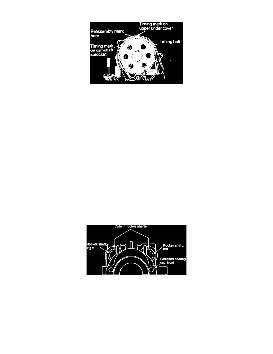
Fig. 4 Camshaft timing marks. 1600cc engines
REMOVAL
1.
Disconnect breather and purge hoses, then remove air cleaner.
2.
Disconnect spark plug wires at spark plugs, then remove upper timing belt cover.
3.
Rotate crankshaft until camshaft sprocket mark is aligned with mark on timing belt upper under cover,. This will position No. 1 cylinder at top
dead center compression stroke.
4.
Place alignment mark on timing belt in line with mark on camshaft sprocket.
5.
Remove camshaft sprocket attaching bolt, then remove camshaft sprocket with timing belt attached to sprocket. The timing belt lower cover
incorporates a sprocket holder which will hold camshaft sprocket in position. If clearance between sprocket and holder is excessive, insert a piece
of timing belt approximately 2 inches long or other suitable material between sprocket and holder. This will prevent the timing belt from becoming
dislodged from the crankshaft sprocket. After sprocket has been removed from camshaft, use care not to rotate crankshaft.
6.
Remove camshaft spacer if equipped, then remove upper timing belt under cover.
7.
Remove rocker arm cover and gasket, then remove camshaft bearing attaching bolts.
8.
Remove rocker arms, rocker shafts and camshaft bearing caps as an assembly from cylinder head. Remove camshaft bearing cap bolts, then
remove bearing caps, rocker arms and springs from rocker shafts.
9.
On models less silent shaft, remove oil seal, distributor drive gear and camshaft as an assembly, then remove oil seal and distributor drive gear
from camshaft.
10.
On models with silent shaft, remove oil seal and distributor drive gear from camshaft, then remove camshaft from cylinder head.
INSTALLATION
1.
Lubricate camshaft lobes and bearing surfaces with engine oil. Then position camshaft on cylinder head.
2.
Check camshaft endplay, which should be 0.002 to 0.006 inch.
3.
If removed, position distributor drive gear on camshaft.
Fig. 17 Rocker arm shaft installation, 1600cc, 2000cc engines
4.
On all models, position intake and exhaust rocker shafts into front camshaft bearing cap. Position shafts as shown in Fig. 17. Install bearing cap
bolts retaining shafts in position.
5.
Assemble rocker arms, spring and bearing caps. After installing rear camshaft bearing caps, insert bolts through rear bearing caps to retain rocker
shaft components. When installing rocker arms, note that intake rocker arms have two adjusting screws.