
Colt L4-1597cc 1.6L SOHC Turbo (1985)
11. Indication of Spare Terminals of Connector:
In the connector diagram a spare terminal is indicated by - A connector terminal marked X or blackened indicates a guide provided to prevent
improper connection.
Installing A Radio on A Vehicle Equipped With Computer
The computer (control unit) has been designed so that external radio waves will not interfere with its operation. However, if a radio (transmitter,
transceiver, etc...) is installed in the vehicle, the radio waves might affect the operation of the control unit.
Mount the radio and the antenna as far as possible from the control unit.
Because radio waves are emitted from the coaxial cable of the antenna, keep it as far as possible from the control unit and the wiring harness. If the cable
must cross the wiring harness, route it so that it runs at right angles to the wiring harness. The antenna and the cable should be well matched, and the
standing-wave ratio* should be kept low. A radio (transmitter, transceiver, etc...) having a large output should not be installed in the vehicle. (The
maximum output of the unit being installed should be low or less.)
After installing the radio unit, transmit a test wave while the engine is idling, and confirm that the engine is not affected.
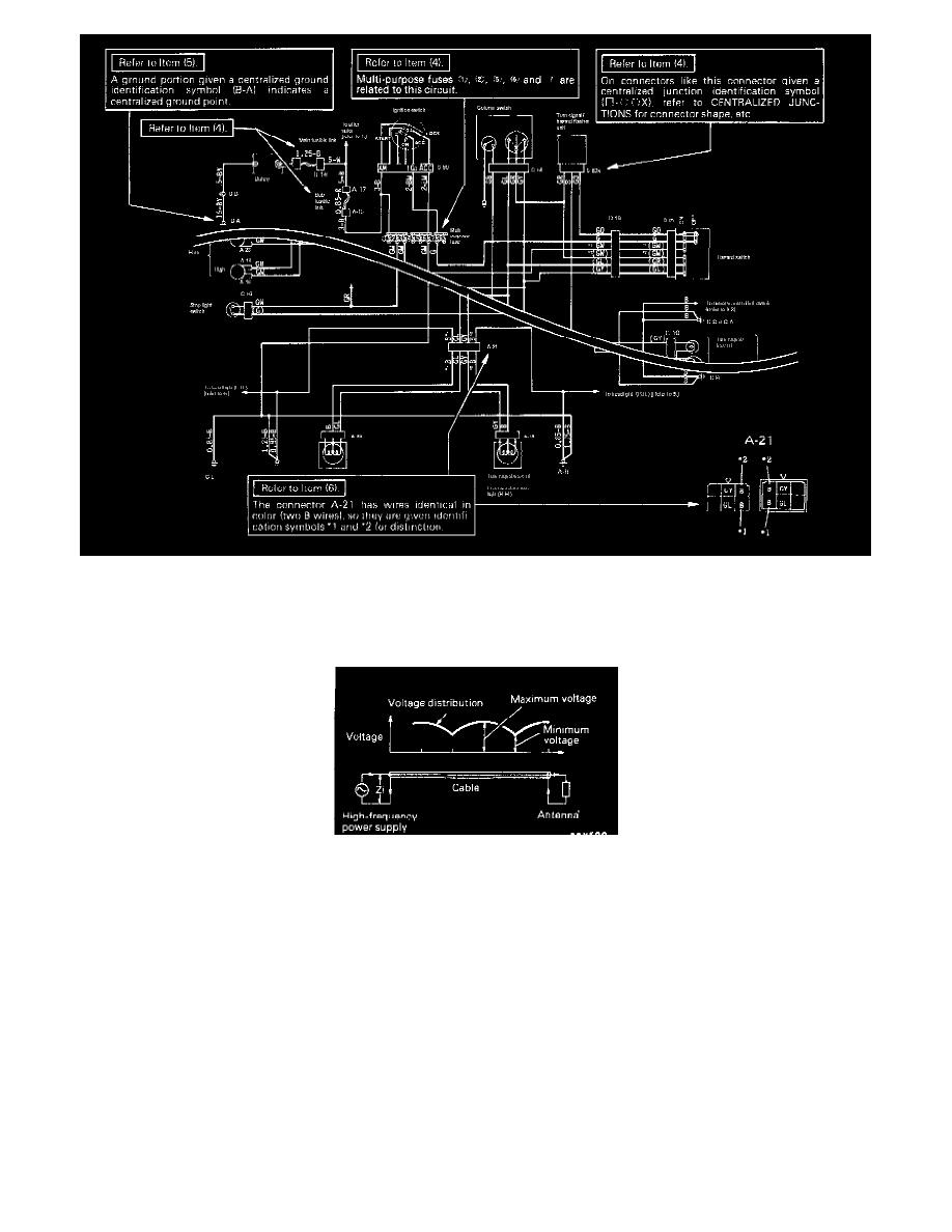
* Standing-wave ratio:
If an antenna and a cable having different impedances are connected, the input impedance Zi will vary in accordance with the length of the cable and the
frequency of the transmitter, and the voltage distribution will also vary in accordance with the location.
The ratio between this maximum voltage and minimum voltage is called the standing-wave ratio. It can also be represented by the ratio between the
impedances of the antenna and the cable.