
Colt L4-1597cc 1.6L SOHC Turbo (1985)
The circuit diagrams by functions show the electrical wiring circuits of vehicles as classified by their functional systems. For those circuits which vary
according to vehicle specifications, further division by the functional systems is made.
The harness connectors included in the circuit diagrams are also shown to facilitate comparison with the circuit diagrams.
The fuse specifications and mounting positions are shown in GENERAL, whereas the centralized connectors (fuses and relays centralized at one
location) are collectively shown in CENTRALIZED JUNCTION.
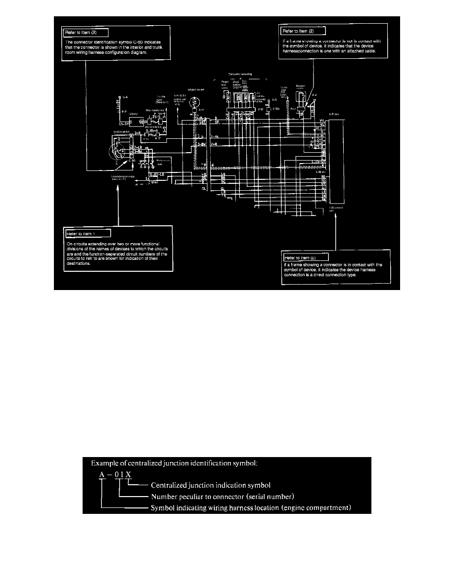
1. Indication of Circuits Extending Over Two or More Functional Divisions:
A circuit diagram shows a function-separated circuit from the power supply to the ground. On circuits extending over two or more functional
divisions, their destinations are shown so that the mating circuit diagrams can be referred to.
2. Indication of Device Connections:
The circuit diagrams are so made as to show whether the device is attached with wiring or it is designed for direct plug-in.
3. Indication of Connectors in Circuit Diagrams:
A connector in a circuit diagram is shown in a frame and given a connector identification symbol for ease of comparison with connector diagrams
and wiring harness diagrams.
4. Indication of Fuses and Centralized Relays:
In the circuit diagrams, fuses are indicated by a waved symbol (~) and the fusible links by a double waved symbol (~).
The fuses in the centralized junction section are given identification numbers (fuse numbers) to allow reference to the centralized junction. The
connectors for centralized relays are also given centralized junction identification symbols to allow reference to the centralized junction.