
Colt Vista 2WD L4-1795cc 1.8L SOHC (1992)
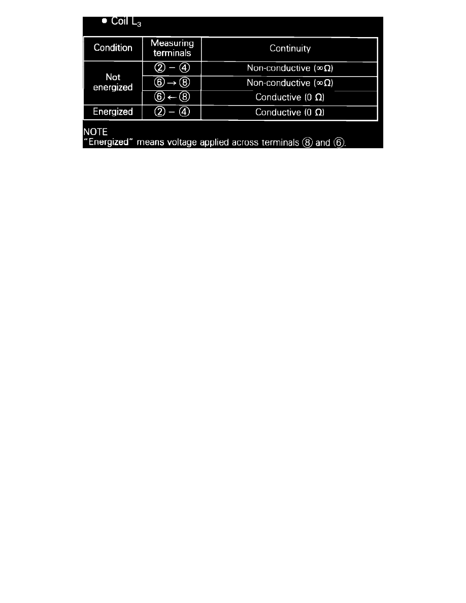
Figure 17. Coil L3
3.
Check continuity between control relay terminals, with relay coil energized and not energized as shown. To energize coil, L3, apply battery
voltage across terminals 8 and 6.
4.
If test results are not satisfactory, replace control relay.