
Colt Vista 4WD L4-1997cc 2.0L SOHC (1985)
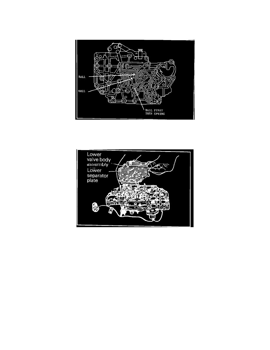
FIGURE 3
5.
Install the end cover and tighten the three attaching bolts to 52 inch pounds.
6.
Assemble the lower valve body and lower separator plate, making sure the stopper plate is installed (Figure 3).
FIGURE 4
7.
Using petroleum jelly to hold them in place during assembly, install the three steel balls and spring removed in Step 2 into the lower side of
the upper valve body (Figure 4).
FIGURE 5
8.
Install the lower valve body and separator plate assembly to the upper valve body (Figure 5). Torque the 13 bolts to 52 inch pounds.
9.
Loosen the solenoid mounting bolts and remove the solenoid valve.
10.
Apply Dextron II to the O-ring and install the new solenoid valve, PN MD727245. Torque the mounting bolts to 52 inch pounds.
11.
Install the filter and oil pan per service manual procedures.
POLICY:
Reimbursable within the provisions of the warranty
TIME ALLOWANCE:
Labor Operation No.
21-95-01-90 . . . . . . . . . . . .1.4 Hrs.
FAILURE CODE:
RO - Driveability