
Colt Vista AWD L4-1795cc 1.8L SOHC (1992)
Main Relay (Computer/Fuel System): Testing and Inspection
CAUTION:
a.
When applying battery voltage to the Control Relay, verify power source connections are to the correct terminals. Otherwise, the Control
Relay will be damaged.
b.
The following test procedures should be performed in the order instructed. If not, inaccurate results and damage to the relay may occur.
Control Relay
1.
Disconnect the Control Relay electrical connector, and remove the relay.
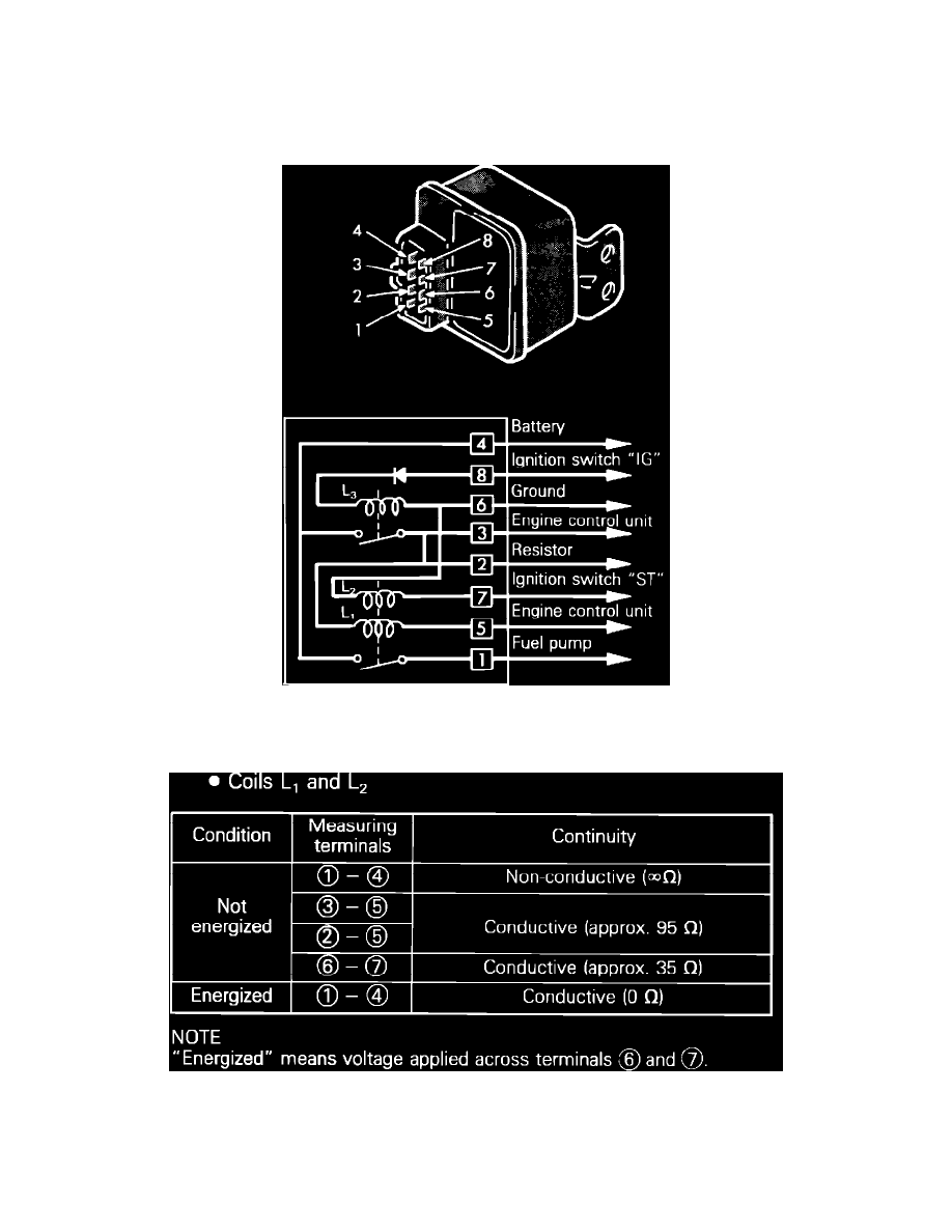
Figure 16. Coil L1 & L2
2.
Check continuity between control relay terminals, with relay coil energized and not energized as shown. To energize coils, L1 and L2, apply
battery voltage across terminals 6 and 7.