
Colt Vista FWD L4-1795cc 1.8L SOHC (1994)
Body Control Module: Diagram Information and Instructions
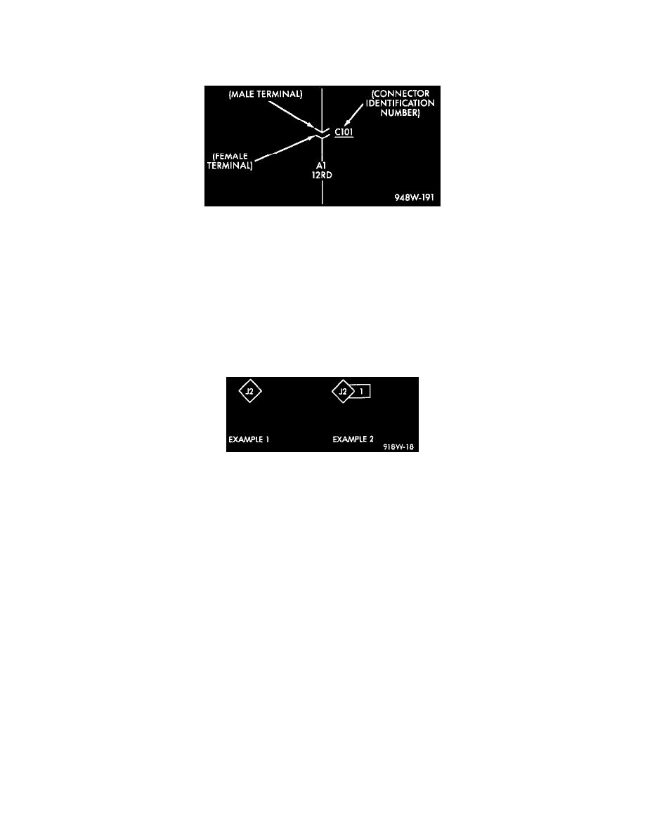
Connector Information
Connector Identification
Connectors shown in the diagrams are identified using the international standard arrows for male and female terminals. A connector identifier is placed
next to the arrows to indicate the connector number.
For viewing connector pin-outs, with two or more terminals, refer to Connector Pin-Outs Index, which identifies the connector by number and provides
terminal numbering, circuit identification, wire colors, and functions.
All connectors are viewed from the terminal end unless otherwise specified. To find the connector location in the vehicle, refer to Connector Locations
Index, which uses the connector identification number from the wiring diagrams to provide a figure number reference.
Splice Location Symbol Identification
Wiring Splice Examples
Splice locations are indicated in the diagrams by a diamond with a splice circuit code within it (example 1). If there is more than one splice per
circuit a small box will be connected to it with the splice number in it (example 2).
To locate a splice in the wiring harness determine the splice number from the diagrams then refer to Locations/Splices. This section shows the
general location of the splice in the harness.