
Colt Vista FWD L4-1795cc 1.8L SOHC (1994)
Ignition Relay: Testing and Inspection
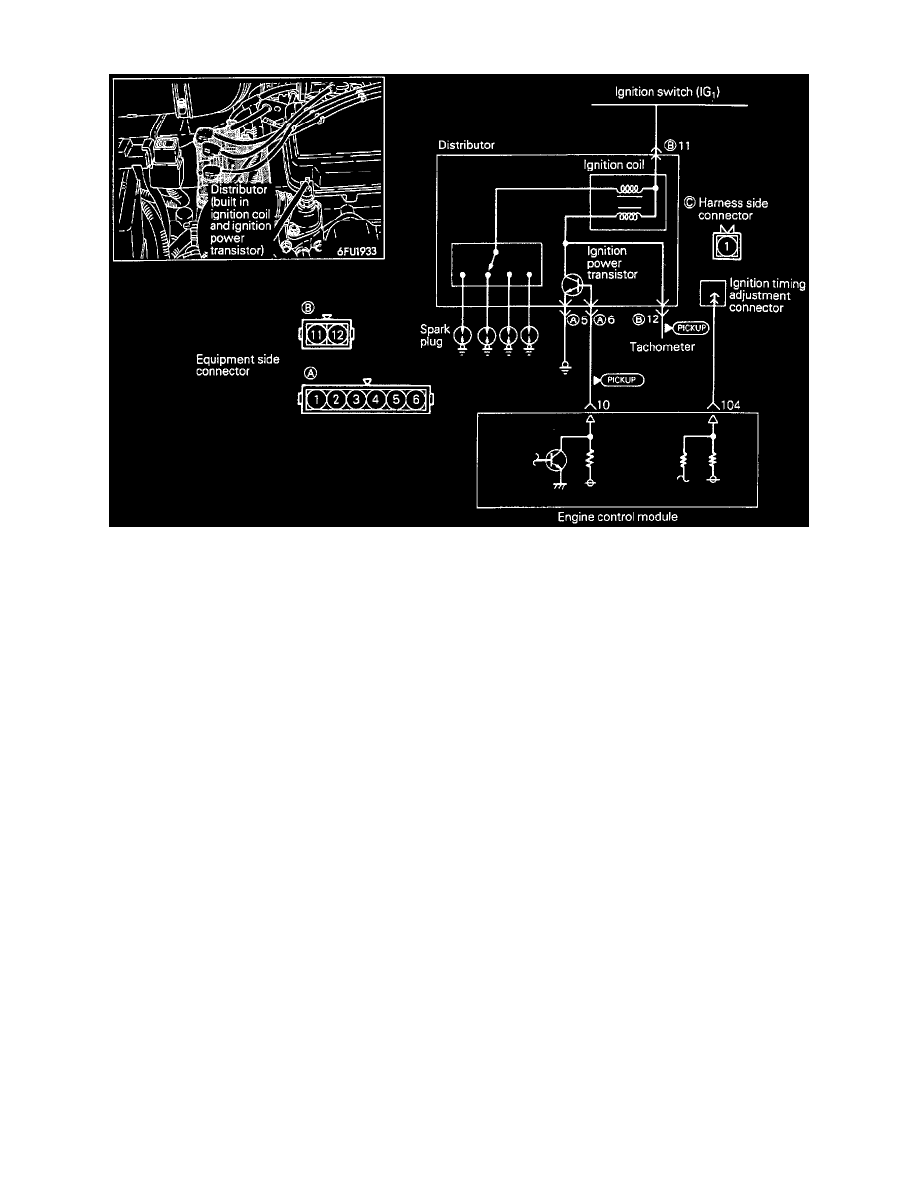
Ignition Coil And Power Transistor
Wave Pattern Inspection Using an Analyzer
-
Ignition coil primary signal
Refer to GROUP 8-Ignition System
-
Ignition power transistor control signal
Measurement method
1. Disconnect the ignition power transistor connector, and connect the special tool (test harness: MB991348) in between.
(All terminals should be connected.)
2. Connect the analyzer special patterns pickup to ignition power transistor unit connector terminal ®.
Alternate method (test harness not available)
1. Connect analyzer special patterns pickup to ECM terminals 10 for ignition power transistor.
Examples of abnormal wave patterns
-
Example 1
Wave pattern during engine cranking
Cause of problem
Open-circuit in ignition primary circuit
Wave pattern characteristics
Top-right part of the build-up section cannot be seen, and voltage value is approximately 2V too low.
-
Example 2