
Colt Vista FWD L4-1795cc 1.8L SOHC (1994)
Band Apply Servo: Adjustments
1. Thoroughly clean area around kickdown servo cover.
2. Remove snap ring, then kickdown servo switch.
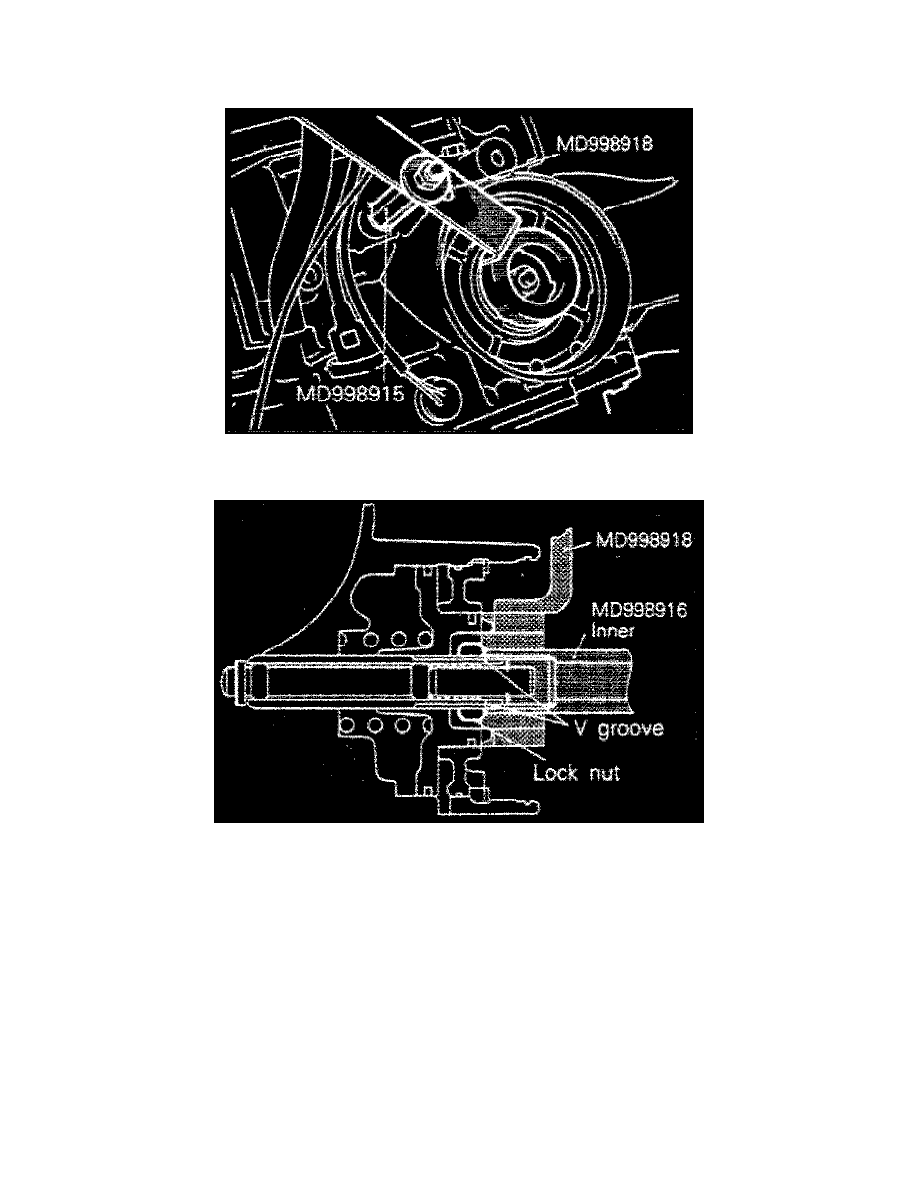
3. Install holding fixture tool No. MD998918 and adapter MD998915, or equivalent, as shown in Fig.3. Ensure piston is not pushed in by tool.
When installing adapter to brake pressure output port, tighten only by hand.
4. Loosen locknut past V channel in adjuster rod, then tighten tool No. MD998916, or equivalent, (inner) until there is contact with locknut Fig.4.
5. Attach tool No. MD998916 (outer), or equivalent, to locknut. Turn outer tool to left and inner tool to right to lock locknut and inner tool.
6. Install torque wrench to inner tool. Torque locknut to 7.2 ft. lbs., then loosen locknut and retorque to 3.6 ft. lbs. Back off inner tool by 2 - 2 1/4
turns on all models except F4A23, on F4A23 back off inner tool by 2 1/2 - 2 3/4 turns.
7. Attach outer tool to locknut. Turn outer tool to right and inner tool to left to unlock locknut and inner tool.
8. Tighten locknut by hand until it contacts piston. Using torque wrench, torque locknut to 18-23 ft. lbs.
9. Remove holding fixture, then install a plug to outlet of low reverse pressure port.