
Colt Wagon 2WD L4-1468cc 1.5L SOHC (1990)
Idle Position Switch: Customer Interest
Idle Speed Position Sensor - MIL ON/DTC 15 Set
NO: 18-19-94
GROUP: Vehicle Performance
DATE: Oct. 7, 1994
SUBJECT:
Check Engine Light On, Fault Code 15, Idle Speed Position Sensor
MODELS:
1990 - 1994 (BD) Laser/Talon w/1.8L SOHC Engine
1990 - 1992 (B2) Colt/Summit w/1.5L Engine
SYMPTOM/CONDITION:
Intermittent rough idle or drive way die out with fault code 15 (idle speed control motor position sensor) set and the Check Engine Lamp may be
illuminated.
DIAGNOSIS:
1.
Use the 1993 Laser/Talon Electrical Service Manual, Volume - 2 (Publication No. 81-270-3501), for reference and inspect the condition of the 5
engine compartment ground connections as shown on Page 8-4. Also, check the condition of the ECU ground connection (Illustration # 7 shown
on Page 8-5 of the Service Manual). Disassemble, clean and install/tighten these ground connections.
2.
Test the throttle position sensor and the idle speed control motor position sensor following the procedures listed in the 1993 Laser/Talon Service
Manual (Publication No. 81-270-3500), Pages 14M-48 through 14M-53. Both sensors must test OK. Perform any repairs required prior to
proceeding to the repair procedure.
PARTS REQUIRED:
AR
NPN
Electrical Tape
AR
NPN
Solder - Rosin Core
1
NPN
10" length of 18 Ga. Wire
1
NPN
Electrical Terminal - 8 mm
REPAIR PROCEDURE:
This bulletin involves installing an additional ground lead to a splice connector and soldering a second splice connector.
1.
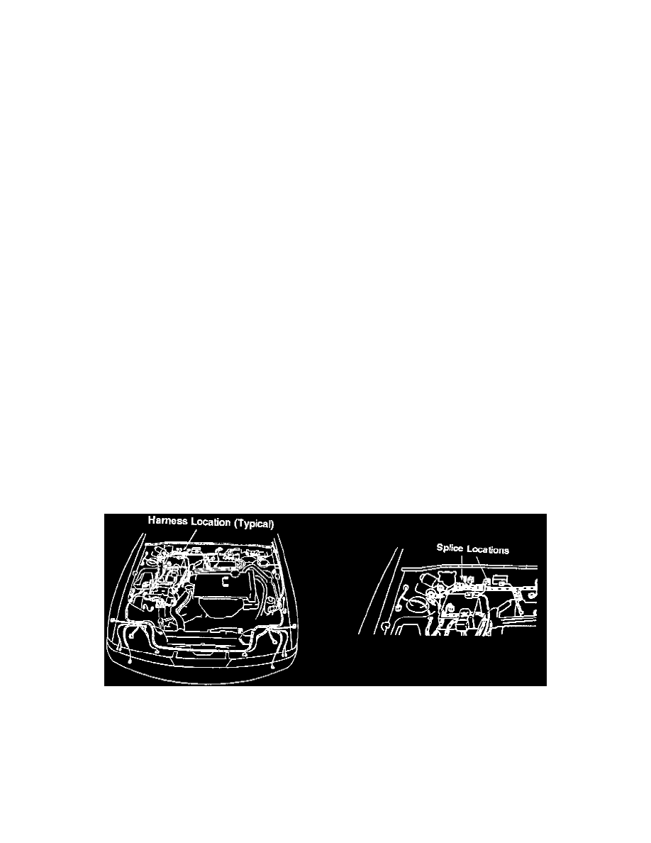
Note the radio station presets and record them. Remove the battery to gain access to the main engine compartment wiring harness that runs along
the top of the engine side of the dash panel.
2.
Remove the tape covering the plastic corrugated harness protector. Uncover the area from behind the battery to the junction where the harness
splits behind the engine.
3.
Isolate the green/black stripe wire in the harness. Follow its length and locate the two taped splice connections. Remove the tape from the splices.