
Colt Wagon 2WD L4-1468cc 1.5L SOHC (1990)
a.
Do NOT remove the throttle valve.
b.
When loosening a Phillips screw which has been tightened firmly, be sure to use a screwdriver that is an exact fit.
c.
Be careful while removing the Throttle Position Sensor screw. It has been coated with an adhesive.
INSTALLATION OF THE TPS TO THE THROTTLE BODY
TPS Temporarily Mounted
1.
Install the TPS on the throttle body and temporarily tighten the screws.
Rechecking The TPS
2.
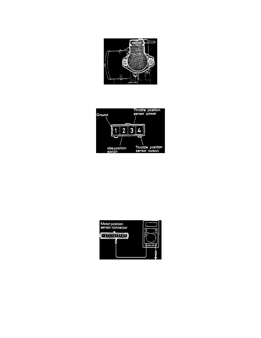
Connect an ohmmeter to terminals # 1 and # 2 of the TPS connector.
3.
Verify that the resistance changes smoothly as the throttle valve is fully opened and closed slowly.
4.
Connect the ohmmeter to terminal # 2 and terminal # 4 of the TPS connector.
5.
Verify that the resistance changes smoothly as the throttle valve is fully opened and closed slowly.
If resistance changes smoothly, then the TPS has been installed correctly.
IDLE POSITION SWITCH CONTINUITY CHECK, after assembly.
Checking The Idle Position Switch
6.
Check for continuity between terminal # 4 and the ground.
^
While the throttle valve is fully closed - continuity should exist.
^
While the throttle valve is fully opened - continuity should NOT exist.
Replace the Idle Speed Control Servo, if the results differ from above.