
Colt Wagon 2WD L4-1468cc 1.5L SOHC (1990)
f.
Assemble pressure rings and their inner parts, friction plates and friction discs together. Measure overall width (E).
g. Obtain clearance (Y) between clutch plate set and differential case as follows. Y = A - (E + Lr + Ll).
h. If clearance (Y) is not 0.0024-0.0098 inch change friction discs.
2. Place each part in differential case as shown.
3. After assembly, inspect rotation torque, as outlined above.
Predisassembly Inspection
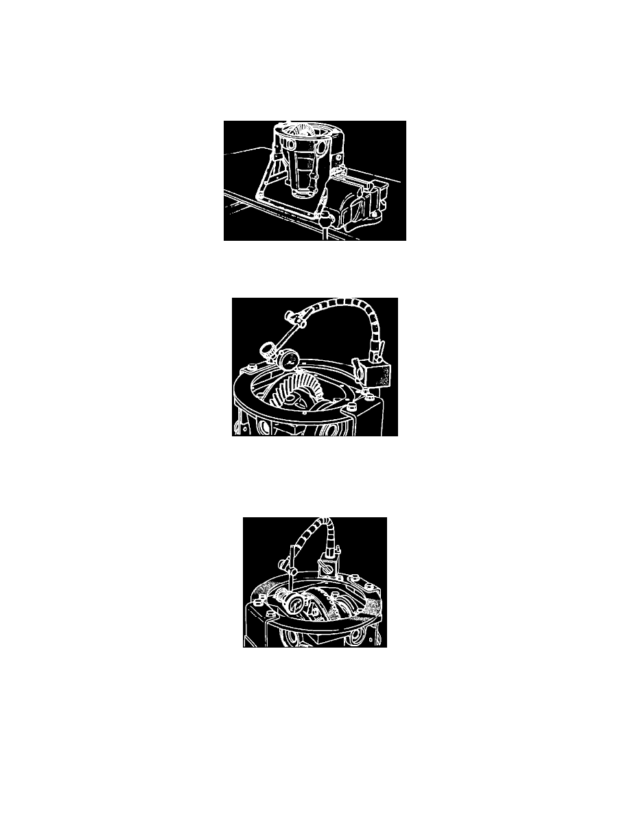
Fig. 28 Positioning Differential Carrier In Working Base
1. Support working base in a vise, and attach differential carrier to working base.
Fig. 29 Final Drive Gear Backlash Measurement
2. Check final drive gear backlash as follows:
a. Lock drive pinion in place, then mount dial indicator as shown.
b. Measure backlash at four points or more on the circumference of the drive gear. Backlash should be within 0.004-0.006 inch.
Fig. 30 Drive Gear Runout Measurement
3. Mount dial indicator as shown, then measure drive gear runout at the shoulder on the reverse side of drive gear. Runout should not exceed 0.002
inch.