
Conquest L4-2555cc 2.6L SOHC Turbo (1984)
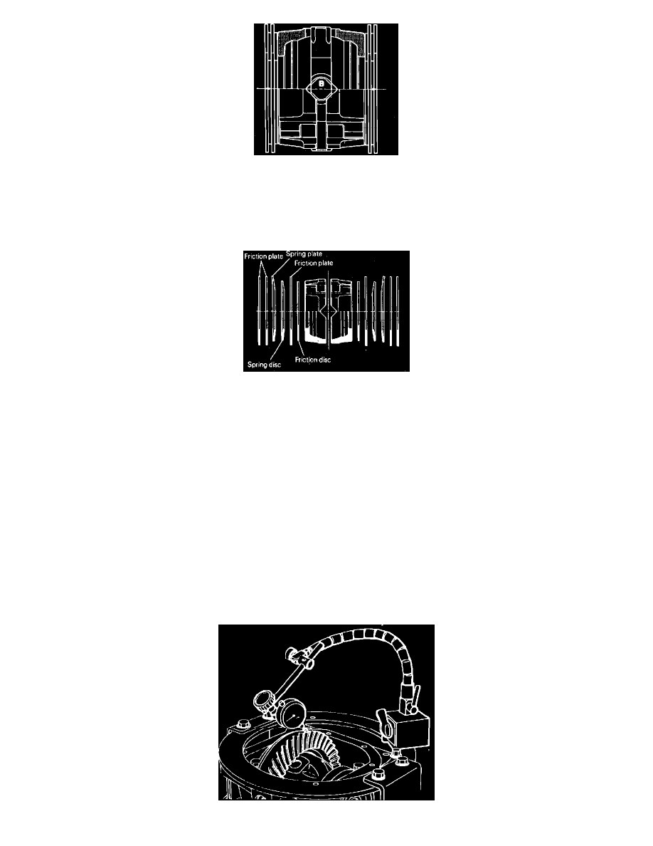
Fig. 9 Measuring pinion shaft & clutch plate assembly width. Limited slip differential
c. Assemble pinion shaft holder, pinion shafts, pressure rings and inner and outer clutch plates, and measure the total width. This measurement
will be considered as value "B."
d. Select shims and adjust so that difference between differential case depth "A" and the sum of values "L," "B" and shim thickness "C"
becomes the standard value.
Fig. 10 Clutch assembly. Limited slip differential
6. On limited slip type units, apply clean gear oil to internal components, then assemble in reverse order of disassembly. Assemble clutch as shown.
7. Thoroughly clean drive gear attaching bolts and remove tape from threaded holes of drive gear using an M10 1.25 tap. Clean the holes with
compressed air.
8. Apply Loctite No. 270, or 271, to drive gear threaded holes, then install gear onto case with reference marks aligned. Torque attaching bolts
alternately, in a diagonal sequence, to 58-65 ft. lbs.
9. Press side bearings into differential case using tool MB990802.
10. Adjust drive gear backlash as follows:
a. Install side bearing adjusting spacers, thinner than those removed, to the side gear bearings, then install differential case assembly into gear
carrier. Select adjusting spacers of the same thickness for both the drive pinion side and the drive gear side.
b. Push differential case to one side and measure clearance between gear carrier and side bearing adjusting spacer using two feeler gauges.
c. Remove side bearing adjusting spacers from one side and measure the thickness of adjusting spacers.
d. To determine proper thickness spacer to be used, add 0.002 inch to thickness measured in step c and one-half the clearance measured in step
b.
e. Install one pair of the correct spacers each to the drive pinion side and drive gear side.
f.
Install differential case assembly, with side bearing adjusting spacers, into gear carrier. Gently tap spacers with a brass drift to seat them on
bearing outer race.
g. Install bearing cap with reference marks aligned. Torque cap bolts to 40-47 ft. lbs.