
Gran Fury L6-225 3.7L VIN J 1-bbl (1983)
Intake Manifold: Service and Repair
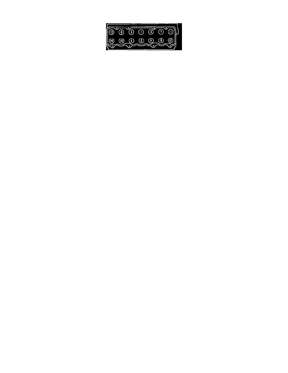
Fig. 1 Cylinder head tightening sequence. 6-225
6-225
1. Drain cooling system.
2. Remove carburetor air cleaner and fuel line.
3. Disconnect accelerator linkage.
4. Remove vacuum control tube at carburetor and distributor.
5. Disconnect spark plug wires, heater hose and clamp holding bypass hose.
6. Disconnect heat indicator sending unit wire. On models equipped with air pump, disconnect diverter valve vacuum line from intake
manifold and remove air tubes from cylinder head.
7. Disconnect exhaust pipe at manifold.
8. On all models, remove closed vent system and rocker arm cover.
9. Remove rocker shaft assembly and pushrods. During disassembly note location of pushrods so they can be installed in the same position.
10. Remove cylinder head bolts, then remove cylinder head and intake and exhaust manifold as an assembly.
11. Install the head in the reverse order of removal, and tighten the bolts in the sequence shown in Fig. 1.
12. When installing the manifolds, loosen the three bolts holding the intake and exhaust manifolds together. This is required to maintain proper
alignment. Install intake and exhaust manifolds with cup side of the conical washers against the manifolds.