
Gran Fury V8-318 5.2L VIN K 2-bbl (1982)
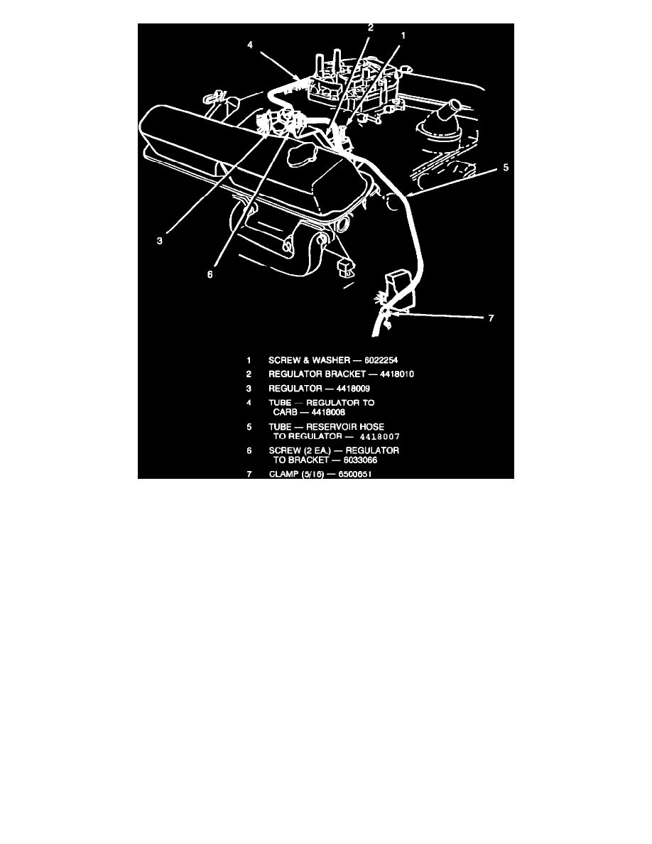
FIGURE - 4FUEL PRESSURE REGULATOR INSTALLATION
2.
Fasten the bracket, PN 4418010, to the fuel pressure regulator, PN 4418009, using the two (2) self-tapping screws supplied, PN 6033066
(Figure 4).
NOTE:
BE SURE THAT OUTLET SIDE OF REGULATOR FACES THE CARBURETOR INLET.
3.
At the tapped boss on the right side of the intake manifold, install bracket and fuel pressure regulator assembly using the screw and
washer, PN 6022254 (Figure 4).
NOTE:
IF THERE EXISTS AN A/C ALTERNATOR BRACKET SUPPORT STRUT IN THIS LOCATION, THEN
LOOSEN THE OPPOSITE END OF THE STRUT FIRST. REMOVE AND DISCARD THE SCREW AND
WASHER HOLDING THE STRUT TO THE MANIFOLD. SLIDE REGULATOR BRACKET UNDER THE
SUPPORT STRUT AND SECURE WITH SUPPLIED SCREW AND WASHER, PN 6022254, THEN TIGHTEN
THE OPPOSITE END OF THE STRUT.
CAUTION:
BE EXTREMELY CAREFUL NOT TO DAMAGE OR PINCH ANY HARNESS IN THE AREA.
4.
Install new tube, PN 4418008, from the regulator outlet to the carburetor inlet. Install new tube, PN 4418007, from the filter outlet hose to the
regulator inlet (Figure 4). Be sure that the tube passes through the clip mounted on the mechanical fuel pump attachment bolt. Slightly compress
clip to secure tube away from any possible interference to nearby components.
5.
Install clamp, PN 6500651, as shown in Figure 4 (filter outlet hose to regulator inlet tube). Rotate clamp so that it is not in contact with any other
surface.
6.
Reconnect the battery terminal. Check wire and hose routing, start the engine, and inspect the entire system for fuel leaks.
POLICY:
Reimbursable within the provisions of the warranty