
Gran Fury V8-318 5.2L VIN K 2-bbl (1982)
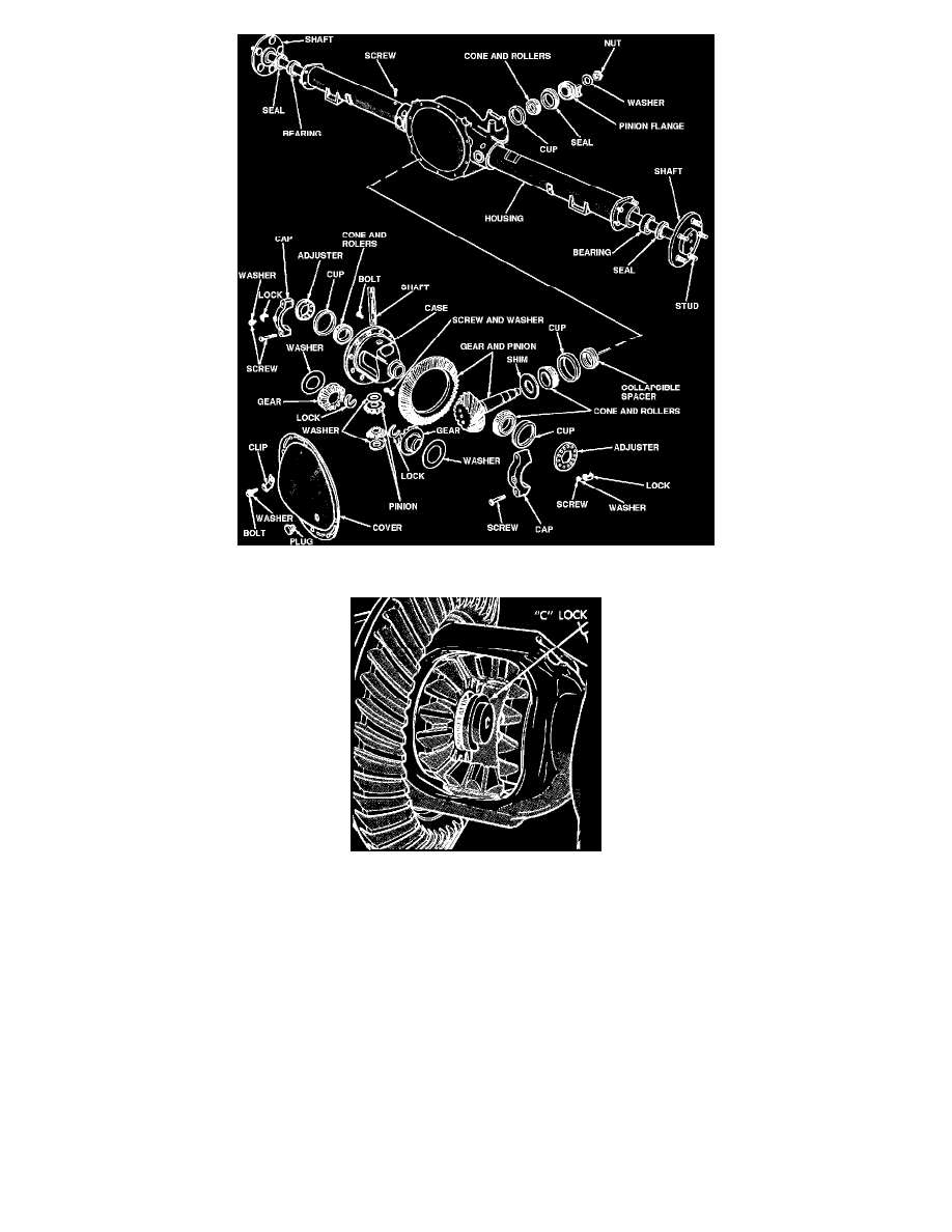
Fig. 3 Integral carrier rear axle exploded view, (type 3). Models w/8-1/4 inch ring gear
Fig. 4 Axle shaft `C' lock installation
The following changes have been made in the design of the 7 1/4 inch rear axle during the 1982 model year for all models except Imperial.
1. The inboard ends of the 8 1/4 inch axle shaft tubes are tapered down in size and pressed into the 7 1/4 inch carrier.
2. The 7 1/4 inch axle shafts ball bearings are replaced with the 8 1/4 inch axle shaft roller bearings.
3. The axle shafts are retained with the standard 8 1/4 inch axle "C" lock washer.
4. The 7 1/4 inch differential side gears now have a counterbore to incorporate the "C" lock washers. These side gears can be used on the early
design 7 1/4 inch axles, but the early design side gears cannot be used on the later design 7 1/4 inch axle.
5. The late design carrier has two cast holes to allow lube to flow into the tubes to lubricate the axle shaft roller bearings.
Servicing the late design 7 1/4 inch rear axle is the same as the early design 7 1/4 differential, except for the axle shaft and axle shaft bearing. When
replacing axle shaft or axle shaft bearing refer to "Axle Shaft, Replace" for service procedures.
Two types of integral carrier axles are used. In both types, the drive pinion is mounted in two opposing tapered roller bearings which are preloaded by
a spacer positioned between them.
In the unit shown the differential is supported by two tapered roller side bearings. These bearings are preloaded by spacers located between the
bearings and carrier housing. The differential assembly is positioned for ring and pinion backlash by varying these spacers.
Axle shafts in this unit are held in place by retainers at the outer ends of the shafts. These retainers are bolted through the brake backing plates to the
rear axle tubes.
In the unit shown the differential is also supported by two tapered roller bearings. A threaded differential bearing adjuster is located in each bearing