
Gran Fury V8-318 5.2L VIN M 4-bbl (1982)
Positive Crankcase Ventilation: Description and Operation
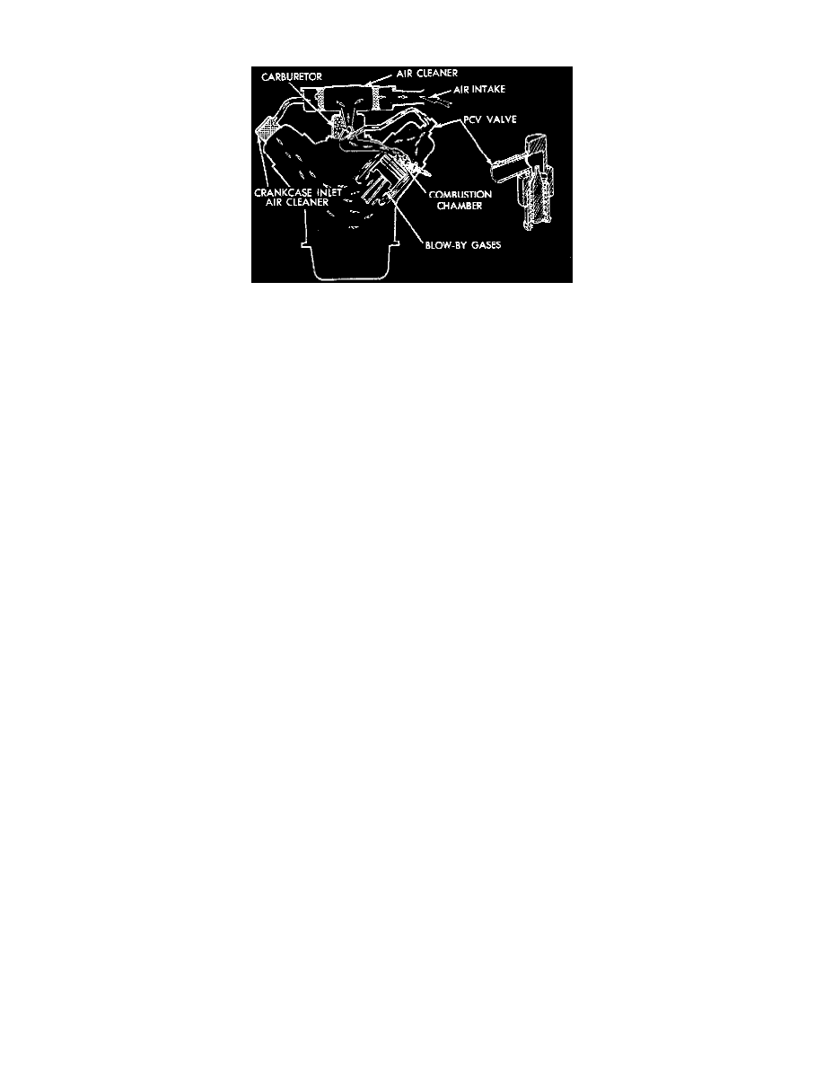
Fig. 33 - PCV System (Typical)
This system. Fig. 33, is used on all engines to prevent the emission of blowby gases from the engine's crankcase. These blow-by gases are the
result of high pressures developed within the combustion chamber during the combustion process and contain undesirable pollutants.
When the engine is running, air is drawn by manifold vacuum from the air cleaner through a hose, to the crankcase inlet air cleaner. From the
crankcase inlet air cleaner, the air mixes with the vapors in the rocker arm chamber and crankcase and are then drawn up through the PCV valve in
the cylinder head cover to a hose connected to either the intake manifold or carburetor base. These gases become part of the calibrated air/fuel
mixture and are then drawn into the combustion chamber, burned and expelled with the exhaust gases.