
Grand Fury/Salon V8-318 5.2L VIN P 2-bbl (1984)
Ball Joint: Service and Repair
Upper Ball Joint Replacement
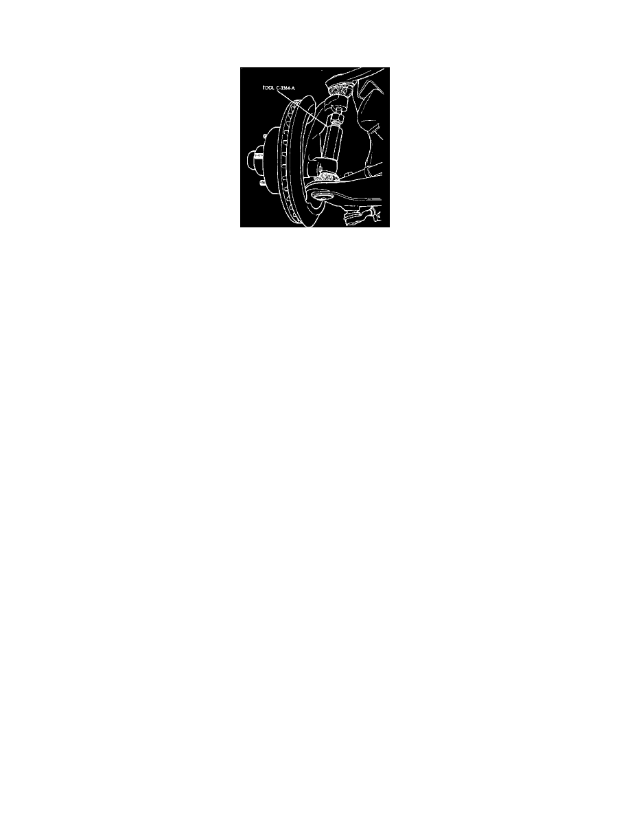
Fig. 6 Removing upper ball joint stud using tool C-3564-A
UPPER BALL JOINT
1. Place ignition switch in the "Off" position.
2. Using a suitable jack raise front of vehicle and position a jack stand under lower control arm as close to wheel and tire assembly as
possible. Check to ensure that jack stand is not in contact with brake splash shield. Also check to ensure that rubber rebound bumper is
not in contact with frame. The torsion bar will remain in the loaded position.
3. Remove wheel and tire assembly.
4. Remove cotter pin and nut from lower ball joint stud. Position tool No. C3564-A over lower ball joint stud, allowing tool to rest on knuckle arm,
then set tool securely against upper ball joint stud.
5. Tighten tool to apply pressure against upper ball joint stud, then strike knuckle with hammer to loosen stud.
6. Remove tool, then detach upper ball joint from knuckle. Support knuckle and brake assembly to prevent damage to lower ball joint and
brake hoses.
7. Remove upper ball joint from upper control arm, using tool No. C3560.
8. Reverse procedure to install. Thread upper ball joint into control arm as far as possible by hand. Torque upper ball joint into control arm to 100 ft.
lbs. After tightening lower ball joint stud nut, install cotter pin. Ball joint seals should be replaced whenever they have been removed.
LOWER BALL JOINT
1. Place ignition switch in the "Off" position.
2. Raise vehicle and support so front suspension is in the full rebound position. Position jack stands under front frame for additional support.
3. Remove wheel and tire assembly, then remove disc brake caliper and support with wire hook to prevent brake hose from becoming damaged.
4. Remove disc brake hub and rotor assembly and splash shield, then disconnect shock absorber at lower mounting.
5. Release load on torsion bar by rotating adjusting bolt counterclockwise.
6. Remove upper and lower ball joint stud nuts and cotter pin, then position tool No. C3564-A over upper ball joint stud so that tool is resting on
steering knuckle.
7. Rotate threaded portion of tool to lock it against lower ball joint stud. Tighten tool to place pressure on lower ball joint stud, then strike steering
knuckle with a hammer to loosen stud. Remove tool and disconnect lower ball joint.
8. Use tool No. C4212 to press ball joint from lower control arm.
9. Position replacement ball joint on lower control arm, then press into control arm using tool No. C4212.
10. Install seal over lower ball joint. Use tool No. C4039 to press retainer portion of seal until it is locked in position.
11. Position lower ball joint to steering knuckle, then install upper and lower stud nuts and torque to 100 ft. lbs. After tightening stud nuts, install
cotter pin.
12. Place tension on torsion bar by rotating adjusting bolt clockwise.
13. Install disc brake assembly and wheel and tire assembly, then adjust front wheel bearing as described under "Wheel Bearings, Adjust."
14. Lubricate ball joint, then lower vehicle and adjust vehicle riding height.