
Grand Fury/Salon V8-318 5.2L VIN R (1985)
H-Valve: Service and Repair
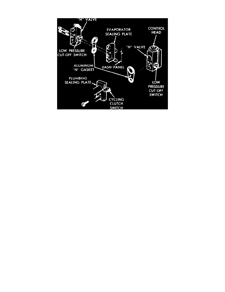
Fig. 10 H-valve assembly (Typical)
1. Discharge system and disconnect wires from low-pressure cut-off switch.
2. Remove bolt in center of plumbing sealing plate.
3. Pull refrigerant line assembly forward taking care not to scratch valve sealing surfaces with tube pilots.
4. Remove two torx head screws while holding valve.
5. Carefully remove valve.
6. Remove and replace aluminum N gaskets on evaporator and plumbing sealing plates.
7. Remove sealing cap from control head side sealing surface of valve, then position valve against evaporator sealing plate and install torx head
screws, torquing to 70-130 inch lbs.
8. Remove sealing cap from plumbing side sealing surface. Hold plumbing up to valve, install 8 mm x 30 mm x 1.25 thread bolt, and torque to
170-230 inch lbs.
9. Connect electrical connector to low pressure cut-out switch.
10. When expansion valve is installed and system charged and leak checked, perform system performance check.