
Grand Fury/Salon V8-318 5.2L VIN R (1985)
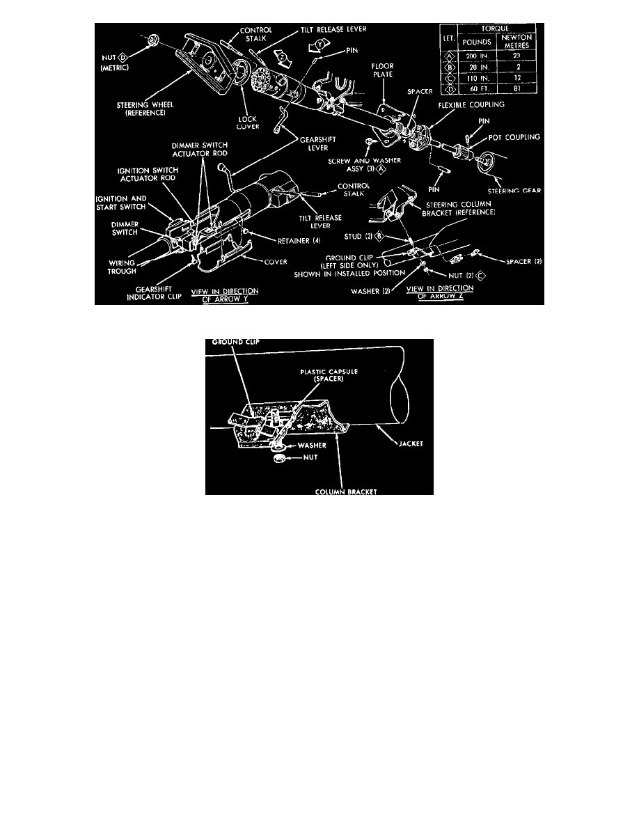
Fig. 2 Steering column installation. 1984---87 RWD models
Fig. 4 Ground clip & capsule installation
4. Making sure that both capsules are fully seated in their slots in the column support bracket, and that the washer makes contact with the ground clip
in the left capsule slot, torque upper bracket retaining nuts to specifications.
5. Place floor plate over floor pan opening, then center it around the column and install the retaining bolts.
6. Install steering wheel and horn switch parts, then connect horn switch wire.
7. Connect wiring connectors to steering column jacket, then connect battery ground cable and check operation of lights and horn.
8. Connect link rods to shift levers by snapping rod into grommet with pliers. Use grease to ease installation. Readjust linkage. Grommet must be
installed into lever before rod is inserted into grommet.
9. On models shown, connect gearshift indicator pointer in approximate original location, then slowly move gearshift lever from 1 (low) to Park
position while pausing briefly at each selector position. The indicator pointer must align with each selector position. If not, loosen the Allen head
screw and readjust to align pointer correctly.
10. On models shown, place gearshift in Drive (third detent from Park) and attach indicator clip to shift housing extension with pointer centered on the
letter "D." Check pointer alignment in all gear positions.
11. Reinstall panel lower reinforcement and cluster bezel or panel lower skirt.
Disassembly
1. Remove column mounting bracket and wire protector and strip wires from protector. Do not damage wires. Unsnap connector from bracket
and tape wires to prevent snagging when removing switch.
2. Remove steering wheel, then loosen the three cover screws and lift cover from housing.
3. Remove tilt release lever and turn signal lever, then depress hazard warning knob and remove knob.
4. Using tool J-23653, depress lock plate and remove wire snap ring from groove shaft, then remove shaft lock, cancelling cam and upper bearing
spring.