
Grand Voyager L4-2.4L DOHC (1996)
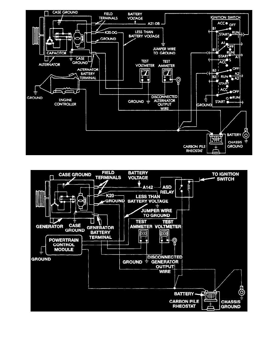
Fig 6 Alternator Current Output Test
Fig 7 Alternator Current Output Test
3. Connect a 0-150 amp D.C. ammeter in series between alternator "B+" terminal and disconnected "B+" lead wire.
4. Connect positive lead of a suitable voltmeter to "B+" terminal of alternator, then connect negative lead to suitable ground.
5. Connect a suitable engine tachometer, then reconnect battery ground cable.
6. Connect a variable carbon pile rheostat between battery terminals, ensuring carbon pile is in Open or Off position.