
Grand Voyager V6-201 3.3L VIN R SMFI (1997)
6.
Remove the screws attaching the front wheelhouse splash shields to gain access to the bolts attaching the front fascia to the fenders.
7.
Remove the bolts (2 each side) attaching the front fascia to the bottom of the fenders.
8.
Remove the 6 bolts attaching the front fascia to the bottom of the radiator closure panel.
9.
Disconnect the fog lamp wiring connectors, if equipped.
10.
Separate the front fascia from the vehicle.
11.
Lower the vehicle to an appropriate height.
12.
Remove the refrigerant line from the filter-drier to condenser.
13.
Disconnect the compressor to condenser refrigerant line from the condenser.
14.
Mark the position of the hood latch, for re-installation purposes, then remove the latch attaching bolts and set the latch aside.
15.
Remove the (4) condenser mounting bolts.
16.
Remove the condenser(s) from the vehicle.
17.
Install a closed cell foam pad to the flush side of both mounting flanges of the transmission auxiliary fluid cooler so they are between the outboard
holes.
18.
For Standard A/C Equipped Vehicles, position the transmission auxiliary fluid cooler with hose nipples pointing down to the face of the condenser
so the edge of the cooler is flush with the drivers side edge of the condenser core and the top mounting flange holes of the cooler are aligned with
the 7th row (from the top) of fins in the condenser core.
For Dual A/C Equipped Vehicles, position the transmission auxiliary fluid cooler with hose nipples pointing up to the face of the condenser so the
edge of the cooler is flush with the drivers side edge of the condenser core and the bottom mounting flange holes of the cooler are aligned with the
2nd (from the bottom) row of fins in the condenser core.
19.
Insert mounting straps from the radiator side of the condenser through the fins and into the two outboard holes in the top flange of the cooler.
Loosely install locks on the mounting straps.
20.
Insert mounting straps from the radiator side of the condenser through the fins and into the two outboard holes in the bottom flange of the cooler.
Install locks on the bottom mounting straps and tighten all the locks against the cooler mounting flanges. Cut the excess mounting strap material
off.
21.
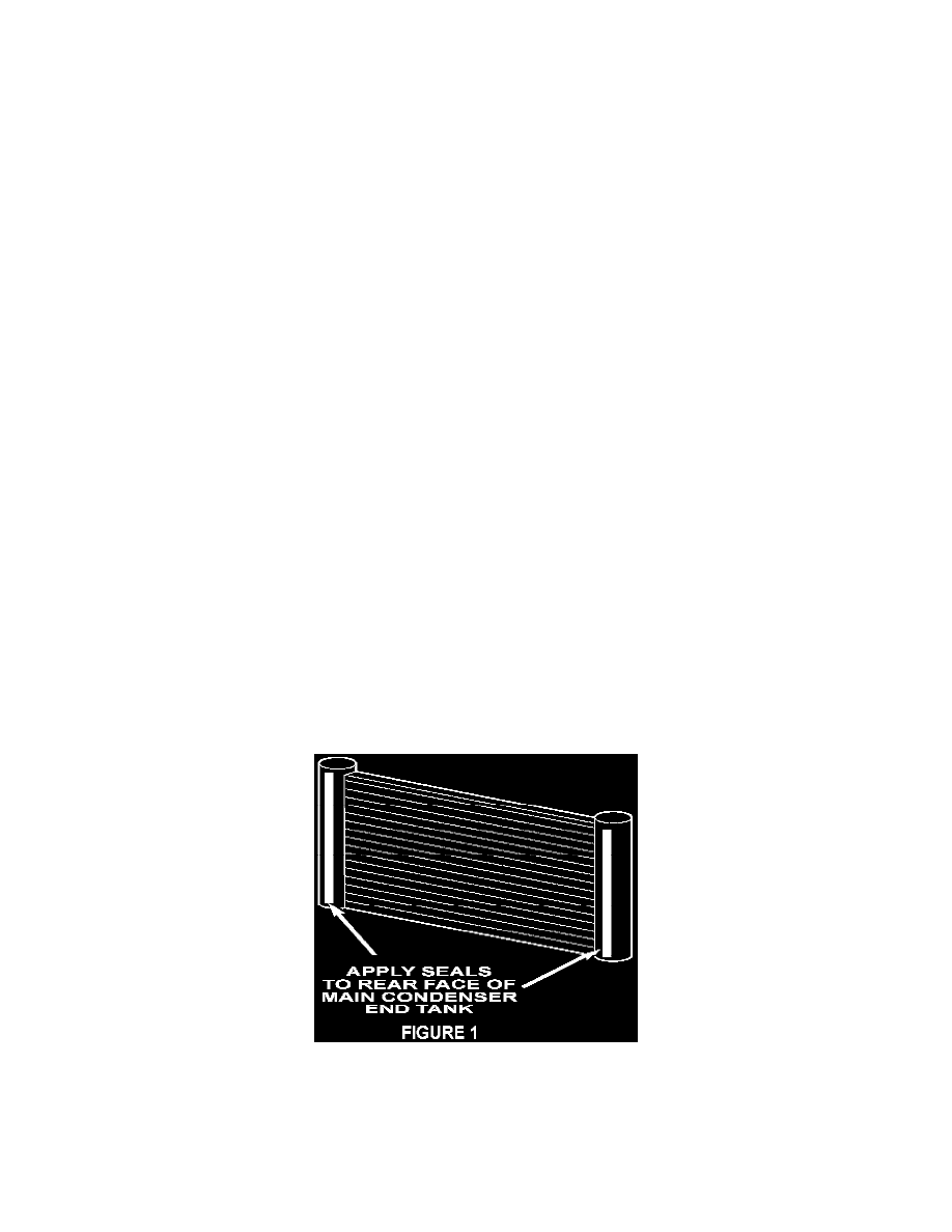
For Standard A/C Equipped Vehicles, install a vertical seal to the face of the radiator side of both main condenser end tanks, Figure 1. Rear A/C
equipped vehicles already have these seals installed.
22.
Install the condenser/auxiliary cooler assembly. Torque the condenser to radiator attaching bolts to 4-6 Nm (35-55 in. lbs.).
23.
Install the upper condenser to radiator air seal. Insure the top surface of the condenser is clean, then remove the backing from the adhesive strip on
the air seal and attach the seal to the top surface of the condenser so the seal covers the gap between the condenser and radiator.