
Grand Voyager V6-3.0L VIN 3 (1998)
Hazard Warning Flasher: Testing and Inspection
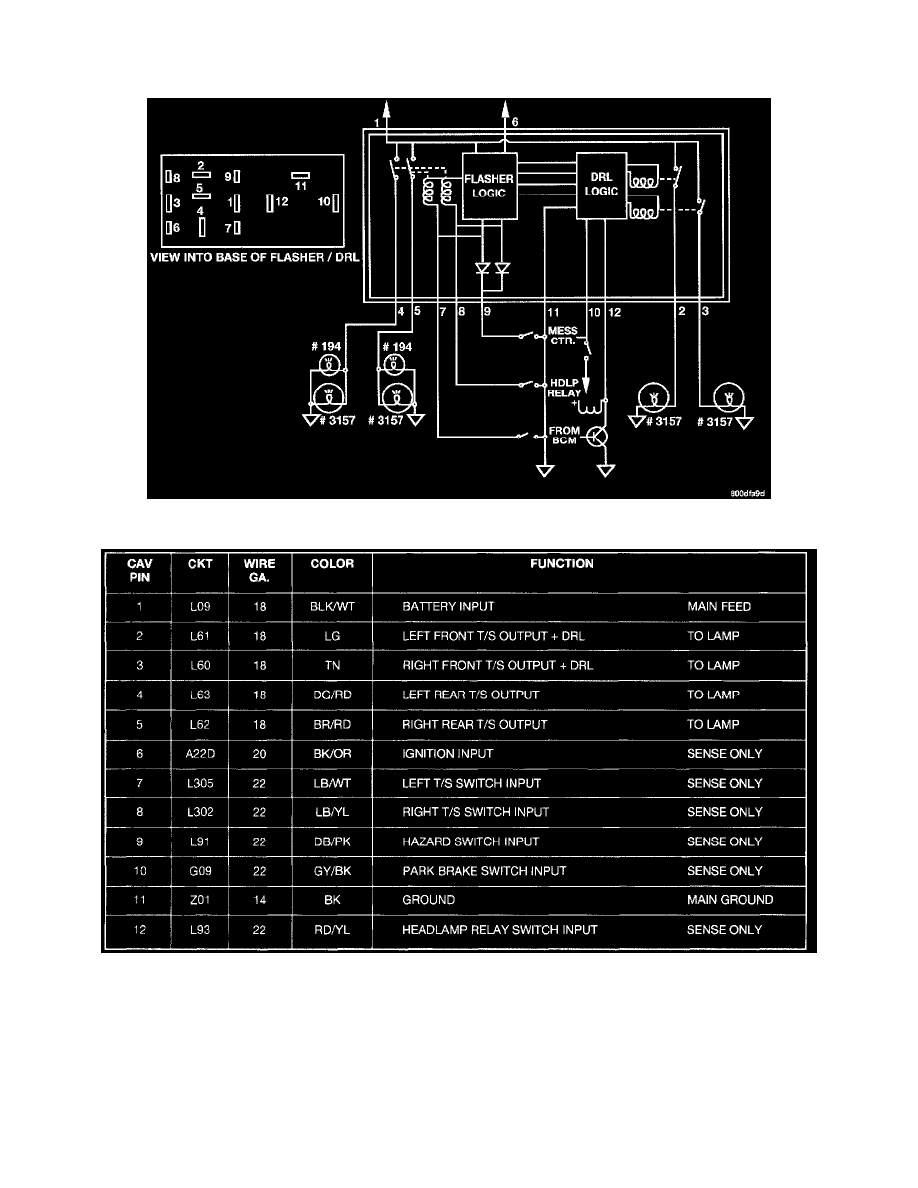
With Daytime Running Lamps Module
Electronic Combination Flasher With DRL Circuit
Junction Block Terminal Call-Out With DRL
The battery input (Pin 1), is brought into the Junction Block through the Electrical Distribution Wiring (EDW) harness through. It originates under
the hood in the Power Distribution Center (PDC) through a 20 ampere fuse at position 10 (9th position from the upper end) and labeled
HAZARD. This circuit (L09) is the only power feed to the combination-flasher/DRL.
The ignition input of Pin 6, only senses that the ignition circuit is ON and does not supply current to the module in a way that would power the
system. This RUN/START circuit is brought into the junction block to a 10 ampere fuse labeled TS BU LMP at the bottom right side. The circuit
designation out of the fuse is A22D.