
Grand Voyager V6-30L VIN 3 (1998) | Powertrain Control Module TSB
3.
Identify the sensor signal terminal. It is terminal No. 4, K41 circuit; 18 gauge black with a dark green tracer (Figure 1).
4.
The connector uses a secondary lock latch at the rear side of the connector. Use a terminal pick or large paper clip and depress the latch while
carefully pulling the secondary cap off the connector. Remove terminal No. 4 by carefully pulling from the rear while spreading the two locking
fingers. Reinstall the secondary cap.
5.
Using the repair lead p/n 05013110AA, insert the new terminal and wire lead into the vacant cavity of the oxygen sensor connector.
6.
Fold the removed oxygen sensor terminal onto itself and place a piece of heat shrink tubing p/n 04778570 over the wire end. Shrink with a heat
gun until sealant flows from both ends. Tape the removed wire out of the way.
7.
Remove the air intake resonator to gain access to the engine wiring harness.
8.
Tape wrap the new lead neatly to the wiring hamess and route it up to the powertrain control module. Make sure the new lead is routed clear of any
moving mechanisms. Use tie straps as necessary for proper routing.
9.
Reinstall the air intake resonator.
10.
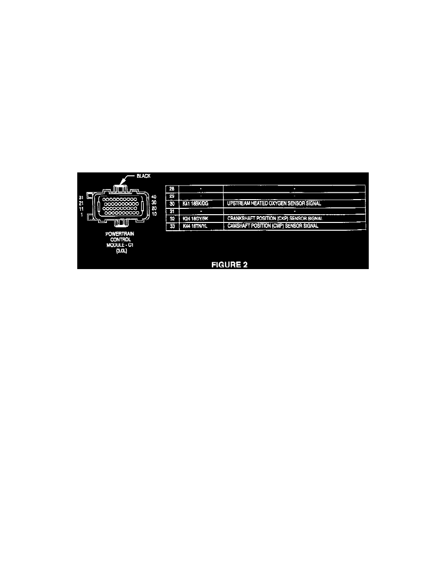
Disconnect the powertrain control module C1 connector (Figure 2).
11.
Remove the wire dress cover from the rear of the C1 connector.
12.
Locate cavity 30 of the C1 connector (K41 circuit BK/DG, Figure 2). Using a terminal pick or small screwdriver, slide the secondary lock over.
Do this by applying force to the side of the lock that does not have the tab. Insert terminal pick Miller Tool 6932 into the slot above the terminal to
be removed. Make sure pick is inserted to its full depth. Hold pick in place while removing the K41 circuit from cavity 30 of the C1 connector.
13.
Fold the removed terminal onto itself and place a piece of heat shrink tubing p/n 04778570 over the wire end. Shrink with a heat gun until sealant
flows from both ends. Tape the removed wire out of the way.
14.
Insert the new terminal and wire lead into cavity 30 of the C1 connector. Using a terminal pick or small screwdriver, slide the secondary lock back
into place.
15.
Reinstall the wire dress cover to the rear of the C1 connector. Using electrical tape p/n 04778138, tape over the repaired area to match the original
construction of the harness finishing the tape on the tape flange of the wire dress cover.
16.
Reconnect the oxygen sensor to its harness and the C1 connector to the powertrain control module.
17.
Reconnect the battery negative cable.
18.
Verify the wiring repair by running the oxygen sensor test with the DRB III.