
Grand Voyager V6-3.3L VIN G Flex Fuel (1999)
Installing Pulley Assembly
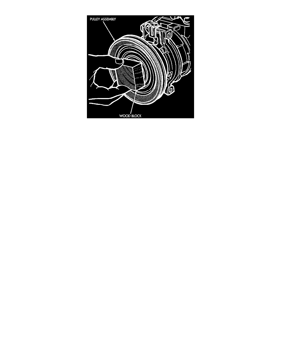
3. Install pulley assembly to compressor. If necessary, tap gently with a block of wood on the friction surface.
CAUTION: Do not mar the pulley frictional surface.
4. Install pulley assembly retaining snap ring (bevel side outward) with snap ring pliers. Press the snap ring to make sure it is properly seated in the
groove.
5. If the original front plate assembly and pulley assembly are to be reused, the old shim(s) can be used. If not, place a trial stack of shims, 1 mm
(0.040 in.) thick, on the shaft against the shoulder.
6. Install front plate assembly onto shaft.
7. With the front plate assembly tight against the shim(s), measure the air gap between front plate and pulley face with feeler gauges. The air gap
should be between 0.5 and 0.9 mm (0.020 and 0.035 inch) If proper air gap is not obtained, add or subtract shims until desired air gap is
obtained.
8. Install compressor shaft bolt. Tighten to 16.5 ± 2 Nm (155 ± 20 in. lbs.).
NOTE: Shims may compress after tightening shaft nut. Check air gap in four or more places to verify if air gap is still correct. Spin pulley for
final check.