
Grand Voyager V6-3.8L VIN L (1999)
Antenna: Testing and Inspection
WARNING: ON VEHICLES EQUIPPED WITH AIR-BAGS, REFER TO AIR BAGS AND SEAT BELTS/AIR BAGS BEFORE
ATTEMPTING ANY STEERING WHEEL, STEERING COLUMN, OR INSTRUMENT PANEL COMPONENT DIAGNOSIS OR SERV1CE.
FAILURE TO TAKE THE PROPER PRECAUTIONS COULD RESULT IN ACCIDENTAL AIRBAG DEPLOYMENT AND POSSIBLE
PERSONAL INJURY.
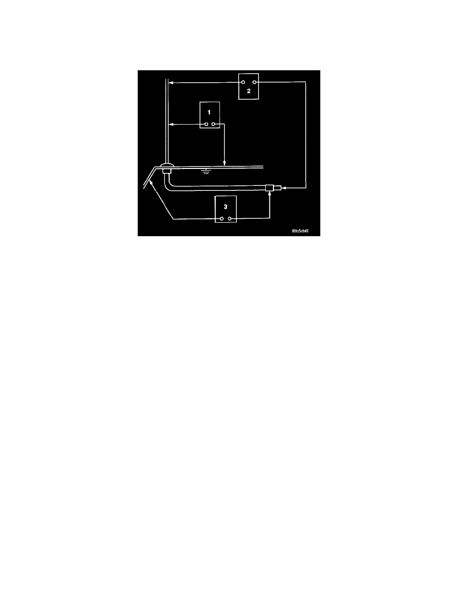
Antenna Test Points
The ohmmeter test lead connections for each test are shown.
TEST 1
Test 1 determines of the antenna mast is insulated from the base. Proceed as follows:
1. Unplug the antenna coaxial cable from the radio chassis and isolate. Remove the antenna mast.
2. Connect an ohmmeter test lead to the inside center of the antenna base. Connect the other test lead to a metallic portion on the outside of the
antenna base. Check for continuity.
3. There should be no continuity. If continuity is found, replace the faulty or damaged antenna base and cable assembly.
TEST 2
Test 2 checks the antenna for an open circuit as follows:
1. Unplug the antenna coaxial cable connector from the radio chassis. Remove the antenna mast. The painted mast prevents measurement directly
through the mast.
2. Connect an ohmmeter test lead to the inside center of the antenna base. Connect the other test lead to the center pin of the antenna coaxial cable
connector.
3. Continuity should exist the ohmmeter should only register a fraction of an ohm). High or infinite resistance indicates damage to the base and cable
assembly. Replace the faulty base and cable if required.
TEST 3
Test 3 checks the condition of the ground between the antenna base and the vehicle body as follows:
1. Connect one ohmmeter test lead to the fender on an exposed metal area paint and e-coat must be penetrated to obtain continuity). Connect the
other test lead to the outer crimp on the antenna coaxial cable connector.
2. The resistance should be less than (1) ohm.
3. If the resistance is more than (1) ohm, clean and/or tighten the antenna base to the fender mounting hardware.