
Grand Voyager V6-3.8L VIN L (1999)
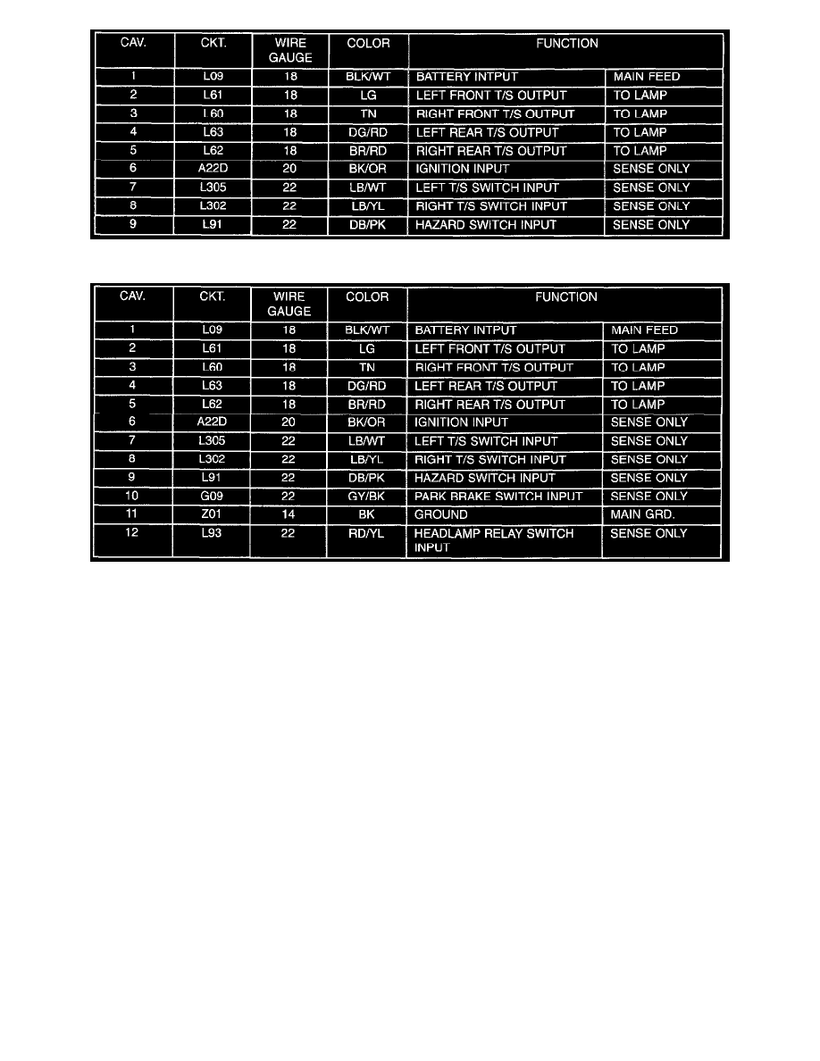
Junction Block Terminal Call-Out
Junction Block Terminal Call-Out With DRL
The ignition input of Pin 6 (refer to Junction Block Terminal Call-Out and Junction Block Terminal Call-Out with DRL tables) only senses that the
ignition circuit is ON and does not supply current to the module in a way that would power the system. This RUN/START circuit is brought into the
junction block to a 10 ampere fuse labeled TS BU LMP at the bottom right side. The circuit designation out of the fuse is A22D. This circuit feeds the
combo-flasher and the following systems with Ignition voltage if the vehicle is so equipped:
-
Back-Up Lamps
-
Electrochromic Inside Rear view Mirror
-
A/C Control Head
-
Mini-Trip Computer
-
ABS Module
-
Front Blower Relay Coil
-
Rear Blower Relay Coil
-
AWD Solenoids
-
Rear Window Defogger (EBL) Relay Coil The ignition input to the combo-flasher will draw typically 5 mA of current while active.