
Grand Voyager V6-3.8L VIN L (1999)
Front Steering Knuckle: Service and Repair
Installation
INSTALLATION
1. Transfer, or install if necessary, a new hub/bearing assembly into the steering knuckle. Refer to Hub And Bearing Assembly Service.
CAUTION: The steering knuckle to strut assembly attaching bolts are serrated and must not be turned during installation. Install nuts while holding
bolts stationary in the steering knuckles.
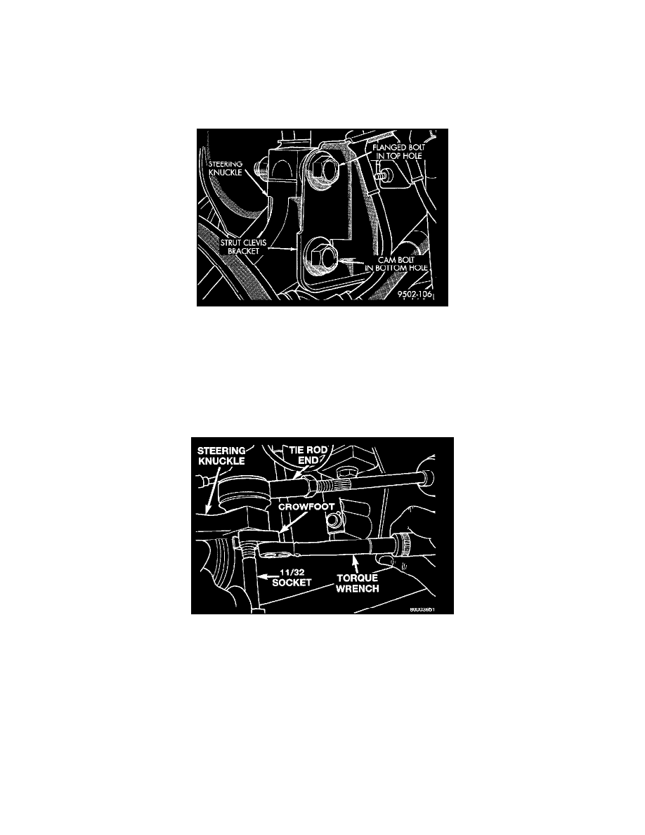
Correctly Installed Eccentric Attaching Bolt
CAUTION: If the vehicle being serviced is equipped with eccentric strut assembly attaching bolts, the eccentric bolt must be installed in the bottom
(slotted) hole on the strut clevis bracket.
2. Install steering knuckle back in clevis bracket of strut damper assembly. Install the strut damper to steering knuckle attaching bolts. Tighten both
attaching bolts to a torque of 90 Nm (65 ft. lbs.) plus an additional 1/4 turn.
3. Slide drive shaft back into front hub and bearing assembly. Then install steering knuckle onto the stud of the ball joint assembly.
4. Install a new steering knuckle to ball joint stud, clamping bolt and nut. Tighten the clamping bolt and nut to a torque of 145 Nm (105 ft. lbs.).
Torquing Tie Rod End Attaching Nut
5. Install tie rod end into steering knuckle. Start attaching nut onto stud of tie rod end. While holding stud of tie rod end stationary using a 11/32
socket, tighten tie rod end to steering knuckle attaching nut. Then using a crowfoot and 11/32 socket, tighten the tie rod end attaching nut to a
torque of 54 Nm (40 ft. lbs.).
6. Install braking disc on hub and bearing assembly.
7. Install disc brake caliper assembly on steering knuckle. Caliper is installed by first sliding bottom of caliper under abutment on steering knuckle,
and then rotating top of caliper against top abutment.
8. Install disc brake caliper assembly to steering knuckle attaching bolts. Tighten the disc brake caliper assembly attaching bolts to a torque of 22 Nm
(195 inch. lbs.).
9. Clean all foreign matter from the threads of the outer C/V joint stub axle. Install the washer and stub axle to hub/bearing assembly nut on stub axle
and securely tighten nut.
10. Install wheel speed sensor and mounting bolt on steering knuckle. Tighten the speed sensor attaching bolt to a torque of 7 Nm (60 inch. lbs.).
11. Install front wheel and tire assembly. Install and tighten the wheel mounting stud nuts in proper sequence until all nuts are torqued to half the
required specification. Then repeat the tightening sequence to the full specified torque of 135 Nm (100 ft. lbs.).