
Grand Voyager AWD V6-201 3.3L (1992)
FRONT MOUNT
1. Support the engine and transmission assembly with a floor jack so it will not rotate.
2. Remove the thorough bolt from the insulator and front crossmember mounting bracket.
3. Remove the front engine mount bracket to front crossmember screws and nuts. Remove the insulator assembly.
4. Reverse removal procedure for installation. Refer to Fig. 3 for bolt tightening specifications.
5. Engine mount adjustment, Refer to Engine Mount Insulator Adjustment below.
LEFT SIDE MOUNT
1. Raise vehicle on hoist and remove left front wheel.
2. Remove inter splash shield.
3. Support the transmission with a transmission jack.
4. Remove the insulator thorough bolt from the mount.
5. Remove the transmission mount fasteners and remove mount.
6. Reverse removal procedure for installation. Refer to Fig. 3 for bolt tightening specifications.
7. Engine mount adjustment, Refer to Engine Mount Insulator Adjustment below.
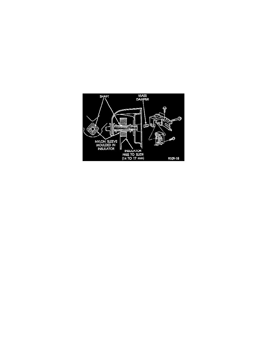
Fig. 4 Left Insulator Movement
ENGINE MOUNT RUBBER INSULATORS
Insulator location on frame rail (right side) and transmission bracket (left side) are adjustable to allow right/left drive train adjustment in relation to
drive shaft assembly length. Check and reposition right engine mount insulator (left engine mount insulator is floating type and will adjust
automatically Fig. 4. Adjust drive train position, if required, for the following conditions:
^
Drive shaft distress.
^
Any front end structural damage (after repair).
^
Insulator replacement.
ENGINE MOUNT INSULATOR ADJUSTMENT
1. Remove the load on the engine motor mounts by carefully supporting the engine and transmission assembly with a floor jack.
2. Loosen the right engine mount insulator vertical fasteners, and the front engine mount bracket to front crossmember screws and nuts.
NOTE: Left engine mount insulator is sleeved over shaft and long support bolt to provide lateral movement adjustment with engine weight
removed or not.
3. Pry the engine right or left as required to achieve the proper drive shaft assembly length. See Transmission and Drivetrain/Drive Axles,
Bearings and Joints for driveshaft identification and related assembly length measuring.
4. Tighten right engine mount insulator vertical bolts to 37 Nm (27 ft.lbs.). Then tighten front engine mount screws and nuts to 54 Nm (40 ft.lbs.)
and center left engine mount insulator.
5. Recheck drive shaft length.