
Horizon L4-97 1.6L SOHC (1984)
Steering Column: Service and Repair
With Tilt
Removal/Installation
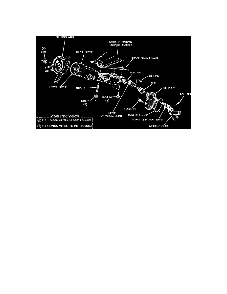
Fig. 5 Steering column installation. Omni & Horizon; 1983---87 Charger & Turismo; 1985---87 Daytona & Laser
HORIZON & OMNI; 1983 - 87 CHARGER & TURISMO; 1985 - 87 DAYTONA & LASER
REMOVAL
1. Disconnect battery ground cable.
2. Disconnect all column wiring connectors.
3. Remove lower roll pin from upper universal joint.
4. Remove the four retaining bolts and remove column from vehicle.
INSTALLATION
1. Align master serrations, then install lower shaft assembly onto steering gear input shaft.
2. Install roll pin into lower universal joint.
3. Snap shaft seal onto toe plate and lubricate inside surface of seal. Slide toe plate over lower shaft and mount toe plate to floor.
4. With column completely assembled and universal joint and spring attached to shaft, hang column to panel by upper righthand mounting point.
5. Unlock key cylinder, then align shaft serrations and mate lower shaft to universal joint.
6. Loosely install the other two mounting bolts and nut, then install the universal joint pin using a back-up to prevent damage to lower bearing.
7. Tighten all column mounting bolts and nuts finger tight, and then loosen two turns. Retighten the lower bolts first, and then the upper nuts so as to
properly align the universal joints.
Disassembly
1. Remove column mounting bracket and wire protector and strip wires from protector. Do not damage wires. Unsnap connector from bracket
and tape wires to prevent snagging when removing switch.
2. Remove steering wheel, then loosen the three cover screws and lift cover from housing.
3. Remove tilt release lever and turn signal lever, then depress hazard warning knob and remove knob.
4. Using tool J-23653, depress lock plate and remove wire snap ring from groove shaft, then remove shaft lock, cancelling cam and upper bearing
spring.
5. Remove the three turn signal retaining screws and pull switch straight out while guiding wires through shroud.
6. Place ignition lock in "run" position.
7. To remove buzzer switch, insert a hooked wire through exposed loop of wedge spring and pull straight out. Remove lock retaining screw from
housing and remove lock cylinder. If lock cylinder is not removed before buzzer switch, buzzer switch must be in the "on" position. If wedge
spring is dropped into column during removal, it may require complete disassembly of column to remove it.
8. Remove cover retaining screws and cover, then remove race and seat from shaft.
9. Reinstall tilt release lever and place column in full "up" position, then remove tilt spring retainer using a screwdriver and depressing retainer about
3/16 inch and turning about 1/8 turn counterclockwise until gears align with grooves in housing and remove spring and guide.
10. With ignition switch in "off-unlock" position, remove ignition switch.