
Steering Column Service and Repair: Horizon L4-97 16L SOHC (1984) | With Tilt
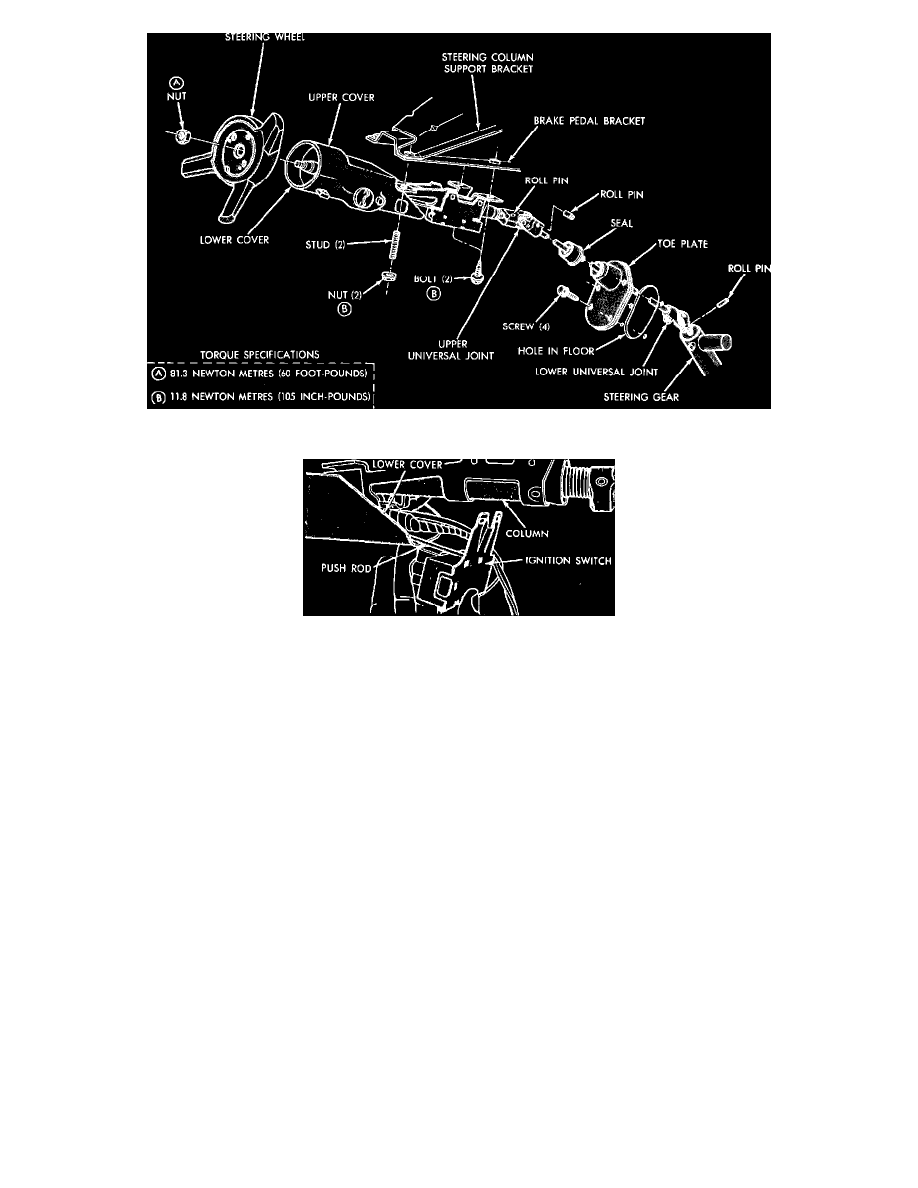
Fig. 5 Steering column installation. Omni & Horizon; 1983---87 Charger & Turismo; 1985---87 Daytona & Laser
Fig. 15 Ignition switch removal, Horizon & Omni; 1983---87 Charger & Turismo; 1985---87 Daytona & Laser
HORIZON & OMNI; 1983 - 87 CHARGER & TURISMO; 1985 - 87 DAYTONA & LAS
1. Disconnect battery ground cable.
2. Remove steering wheel and column covers, key lamp, ignition switch, and dimmer switch, key buzzer switch, washer/wiper switch, key cylinder
and turn signal switch.
3. Unlock key cylinder and carefully remove upper snap ring and steering shaft out through lower end of jacket.
4. To service lower bearing and spring, remove the universal joint.
5. To service upper bearing, remove turn signal switch and gently pry bearing from housing using a flat screwdriver.
6. The inhibitor lever can be removed by removing its retaining screw.
7. The ignition switch pushrod can be removed by unhooking it from ignition switch.
8. The housing assembly is serviced as a unit and should not be removed unless it is to be replaced. The housing assembly can be removed by driving
it off or by splitting it with a hacksaw. If removed, a new housing is required.
9. To remove toe plate, seal and lower shaft assembly, pull back carpeting from toe plate and remove the four screws. Slide toe plate and seal off
shaft. The seal can be removed from plate.
10. Remove lower universal joint retainer (roll pin), to disassemble lower shaft assembly from steering gear.
ASSEMBLY
1. If housing assembly has been removed, install a new housing. Align keyway in jacket with key in housing, the position lock mechanisms so that
lock bolt is withdrawn into housing. Press housing onto jacket until it bottoms. Check to assure that lock mechanism operates smoothly and that
lock bolt extends and withdraws freely.
2. Place upper bearing in place, then mount turn signal switch and retainer plate on housing.
3. Install lower bearing, shaft spring and upper universal joint on lower end of steering shaft, then place lower snap ring in its groove and slide shaft
into lower end of jacket. Compress lower bearing spring and carefully install upper snap ring into groove. Check to make sure that snap ring is
fully seated, and check for proper lock mechanism operation.
4. Install inhibitor lever and spring, ignition switch pushrod, ignition switch, dimmer switch, washer/wiper switch, key lamp, key buzzer switch, key
cylinder, column covers and steering wheel.