
Laser L4-1997cc 2.0L DOHC (1990)
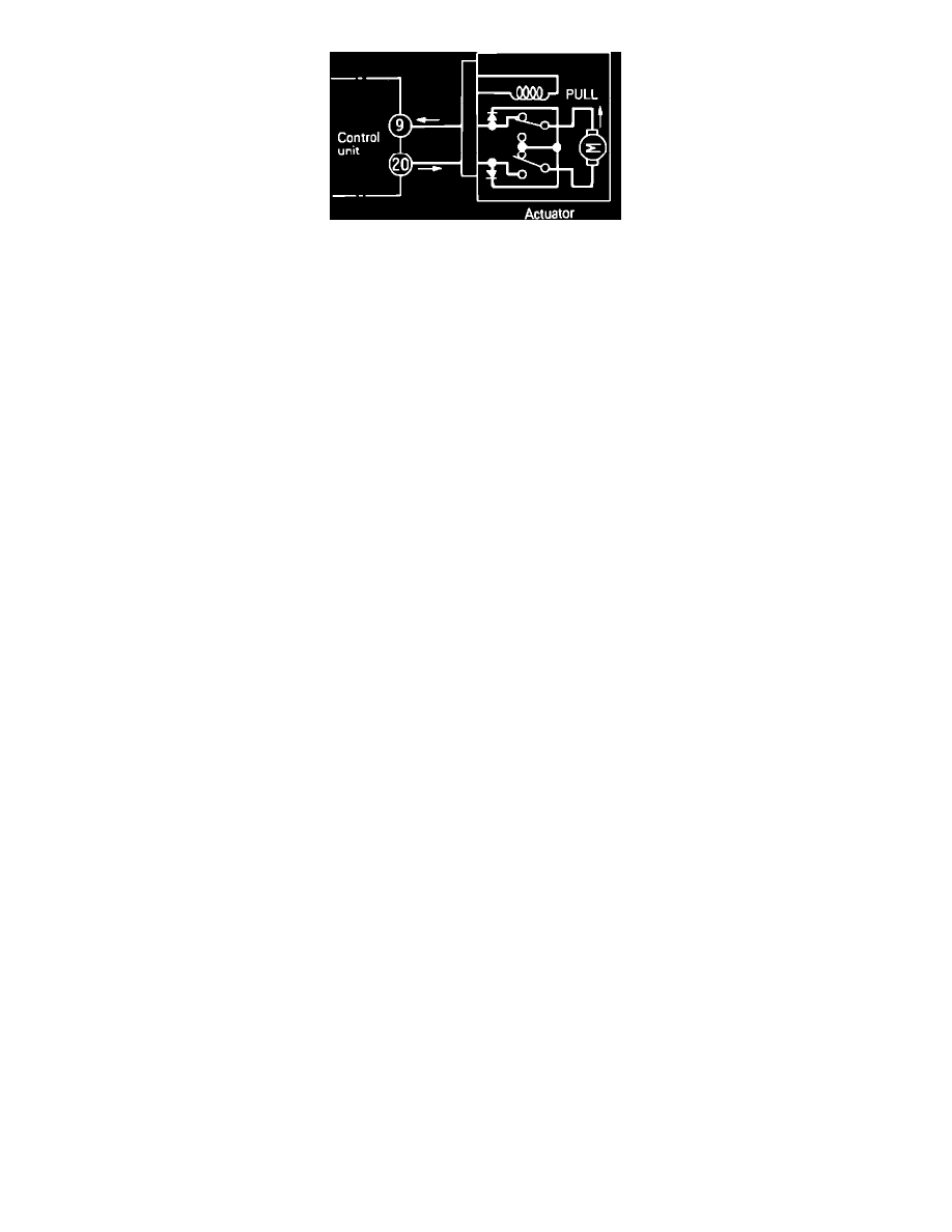
Fig. 95 Actuator Limit Switch
2. The *1 in the tables above indicates that the limit switch within the actuator is positioned as shown. The actuator selector is at the fully closed
position when resistance between terminals 9 and 20 is measured. For this reason, after checking polarity of the tester, the test probe should be
connected so current flows from terminal 20 to terminal 9.
3. For terminals marked *2, it is necessary to check individual terminal voltages with the ECU's harness connector connected and the ignition switch
in the ON position.