
Laser L4-1997cc 2.0L DOHC (1990)
Speed Control Servo: Testing and Inspection
Actuator Operation Test
Fig. 89 Actuator Connector, Single Ammeter
1. Disconnect actuator connector.
2. Connect an ammeter in series with terminal 1 of clutch coil solenoid and battery positive terminal. Connect terminal 2 of clutch coil solenoid to
battery negative terminal.
3. An audible click should be heard and the ammeter should read 0.5-0.7 amps.
4. If the solenoid does not click and the ammeter reads 0.0 amps, the clutch coil or wiring is damaged or disconnected.
5. If the solenoid does not click and the ammeter reads infinite amps, the clutch coil has a short circuit.
Fig. 90 Actuator Connector, Dual Ammeter
6. Do not disconnect ammeter connections from step 2. Using a second ammeter, connect terminal 4 of the actuator through the ammeter, to the
positive battery terminal. Connect terminal 3 of the actuator to the negative battery terminal.
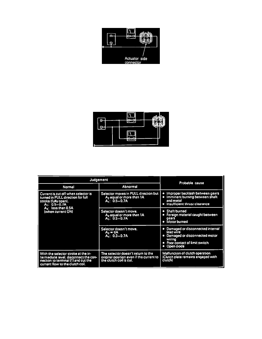
Fig. 91 Actuator Switch PULL Test
7. Refer to chart for conditions and probable causes.