
Laser L4-1997cc 2.0L DOHC (1990)
^
If there is repairable damage to wiring harness repair and retest circuit operation.
^
If there is no visible damage, or damage is not repairable, replace the switch and test circuit operation.
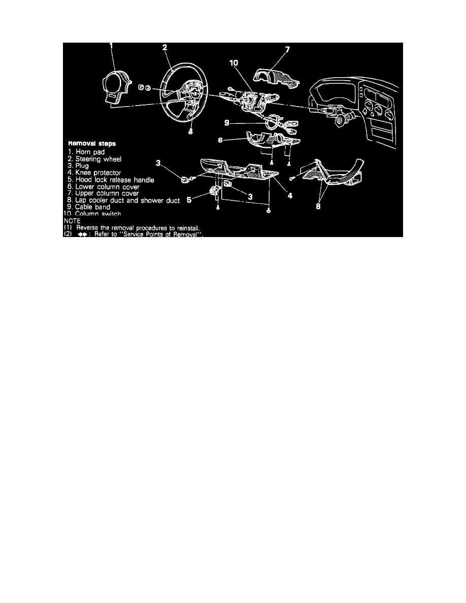
Steering Column
Both Headlamps Will Not Retract
1.
Verify that the pop-up switch is in the "OFF" position.
2.
Check fuse 1 and sub fusible link 4.
^
If fuse 1 is not blown and sub fusible link 4 is good, go to step 7.
^
If fuse 1 is blown go to step 3.
^
If sub fusible link 4 is fused go to step 4.
3.
Place the light switch and the pop-up switch in the "OFF" position and measure the resistance between the switch side of the fuse holder and
ground.
^
If there is continuity to ground, locate and repair short in circuit.
^
If circuit is not shorted to ground, replace the fuse and test circuit operation.
4.
Check for continuity between the sub fusible link 4 load end and ground.
^
If there is continuity, locate and repair short to ground, and test circuit operation.
^
If circuit is not shorted to ground go to step 5.
5.
Inspect the pop-up headlamp mechanism for any obstructions or bent components which would hinder the movement of the headlamps. Repair or
replace any visible problems before proceeding.
6.
Lower headlamps manually to check for binding or mechanical problems.
^
If a mechanism is binding, repair or replace as needed and test circuit operation.
^
If no binding is encountered, replace the sub fusible link, and test circuit operation.
7.
Remove the cluster panel, set the column switch in the "OFF" position, and using a voltmeter or test light, test for voltage at the blue/white wire at
the back of the pop-up switch connector.
^
If there is voltage go to step 8.
^
If there is no voltage present at the pop-up switch, test for voltage in circuit, working back toward the fuse box. Repair open in circuit and
test circuit operation.
8.
If there is voltage present at terminal 1 (blue/white wire) of the pop-up switch, move the probe to the blue/black wire of the pop-up switch
connector, and test for voltage.
^
If there is no voltage present, replace the pop-up switch.
^
If there is voltage present go to step 9.
9.
Move the probe to terminal 5 (blue/black wire) of the passing control relay connector, and test for voltage.
^
If there is no voltage, repair open in wiring between the pop-up switch and the passing control relay and test circuit operation.
^
If there is voltage at terminal 5 (blue/black wire) go to step 10.
10.
Test for voltage at terminal 2 (blue/red wire) of the passing control relay connector.
^
If no voltage is present at terminal 2 (blue/red wire) of the passing control relay connector, replace the passing control relay.
^
If voltage is present at this point go to step 11.
11.
Test for voltage at the pop-up motor connectors (blue/red wires).
^
If no voltage is present at this point repair open in wiring and test circuit operation.
^
If voltage is present at this point go to step 12.