
Laser AWD L4-1997cc 2.0L DOHC Turbo (1992)
23. Center pillar trim
24. Front pillar trim
25. Guide rail <Vehicles for U.S.>
26. Rear belt rail trim <Vehicles for U.S.>
27. Front belt rail trim <Vehicles for U.S.>
REAR PILLAR TRIM REMOVAL STEPS REAR SEAT
1. Scuff plate
5. Quarter trim
20. Coat hanger
23. Center pillar trim
28. Rear pillar trim
LIFTGATE TRIM AND FLANGE TRIM REMOVAL STEPS
29. High mounted stop light cover
30. Liftgate trim
31. Flange trim
NOTE: The * symbol indicates the trim clip.
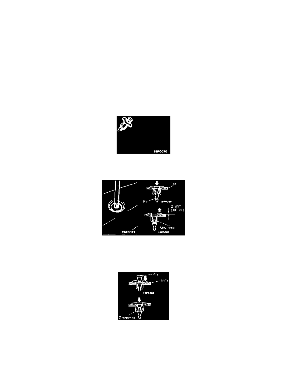
TRIM CLIP REMOVAL/INSTALLATION PROCEDURES
The type of clip shown in the illustration, which is used for the installation of. instrument panel, should be removed and installed by the following
procedures described below.
Removal
1. Use a cross-tip (+) screwdriver to push inward the pin (at the center of the trim clip) to a depth of about 2 mm (.08 in.).
2. Pull the trim clip outward to remove it.
CAUTION: Do not push the pin inward more than necessary because it may damage the grommet, or the pin may fall in, if pushed too far.
Installation
1. With the pin pulled out, insert the trim clip into the hole in the trim.
2. Push the pin inward until the pin's head is flush with the grommet.
3. Check whether the trim is secure.
SERVICE POINTS OF REMOVAL