
Laser AWD L4-1997cc 2.0L DOHC Turbo (1992)
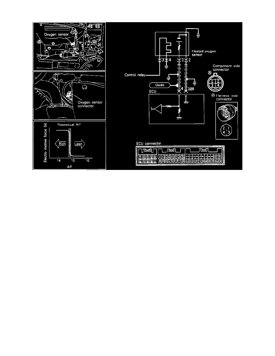
Oxygen Sensor: Testing and Inspection
Heated Oxygen Sensor Circuit
To test the Oxygen Sensor, located on the exhaust manifold, proceed as follows.
SENSOR TEST
1. Start and warm the engine until the coolant temperature exceeds 176°F (80°C).
2. Connect a volt meter with at least 10 megaohm resistance to the #1 terminal at the sensor (do not disconnect the connector).
3. Operate the engine at 4000 rpm and quickly lower the engine to idle.
Voltage:
Approximately 200mV or lower.
4. Operate the engine at idle and observe the volt meter.
Voltage:
Should vary between between 400 mV or lower and 600mV.
5. Operate the engine at 2000 rpm and observe the volt meter.
Voltage:
Should vary between between 400 mV or lower and 600mV.
6. Faulty results in the above test may be caused by:
a. Engine mechanical problems
b. Open or shorted wiring harness
c. Fuel pressure
d. Fuel mixture
7. Perform all tests and see DIAGNOSIS BY SYMPTOM before replacing the sensor.
HEATER TEST
1. Disconnect the O2 sensor connector.
2. Using an ohm meter, check for continuity between O2 sensor connector terminals 3 and 4.