
Laser AWD L4-1997cc 2.0L DOHC Turbo (1992)
Detonation (Knock) Sensor: Testing and Inspection
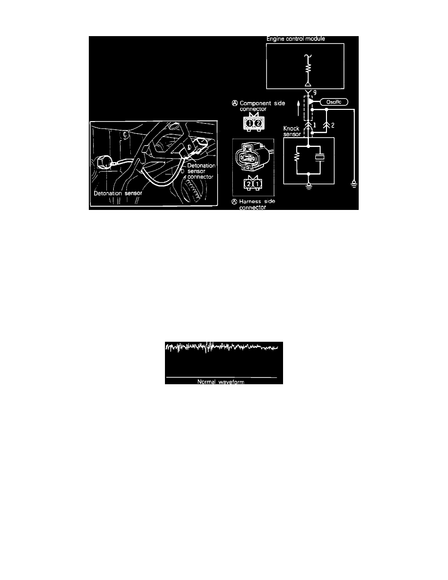
Detonation (Knock) Sensor Circuit
To test the Detonation Sensor and circuit, proceed as follows:
COMPONENT TEST
1. Start and warm the engine to operating temperature.
2. Connect a timing light to the engine cyl #1 and check the timing marks.
3. While watching the timing marks, lightly tap on the cylinder block with a hammer or wrench, next to the sensor.
4. While tapping on the block, the timing should be seen to retard and advance approximately 8° in conjunction with the tapping. If the timing does
not change, then the harness should be tested and checked for continuity or bad connections. If the harness test is OK, replace the sensor.
OSCILLOSC0PE TEST
1. Connect the pick-up lead of an oscilloscope to the #1 terminal of the sensor harness as shown in the image.
2. Start the engine and warm to operating temperature.
Oscilloscope Display
3. Operate the engine at 5000 rpm and observe the scope pattern.
4. If the pattern does not appear similar to the example, check the harness and replace the sensor if the harness checks O.K..
HARNESS TEST
1. Disconnect the sensor connector.
2. Using a voltmeter, check the voltage between the sensor harness terminal 1 and ground.
Voltage
8 - 11 VDC
3. Using an ohm meter, check for continuity between the sensor harness terminal 2 and ground.
Continuity
Should exist
If any of the previous tests produce unsatisfactory results, the harness will need to be repaired or replaced. Once repairs have been completed, clear
the trouble codes and road test the vehicle to confirm that the repair has corrected the problem and the code doesn't return.