
Laser AWD L4-1997cc 2.0L DOHC Turbo (1992)
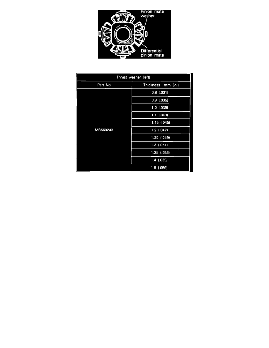
Fig. 64 Differential Pinion Mate Installation
Fig. 65 Thrust Washer Thickness Chart
1. With pinion mate washer in position shown install differential pinion mate to differential pinion shaft, and install in differential case B.
2. If differential side gear and pinion mate gear have been replaced, select left side thrust washer as follows:
a. Wash differential side gear and pinion mate gear in solvent to remove all foreign material.
b. Install previously used thrust washers (matching left and right sides), together with gears, viscous unit, pinion mate washer and pinion shaft to
differential cases A and B. Using screws, secure temporarily.
c. Secure differential case assembly in a vise so that right side differential side gear is facing upward.
CAUTION: Do not hold differential case too tightly.
d. Insert a 0.0012 inch feeler gauge at two places (diagonally) between differential case B and right side thrust washer.
CAUTION: Do not insert feeler gauge in oil groove of differential case B.
e. Insert side gear holding tool No. MB990990 or equivalent at spline part of differential case B (right) and ensure that side gear does not rotate.
f.
Differential gear backlash (clearance in thrust direction of side gear) should be within 0.0012-0.0035 inch (0.03 mm-0.09 mm). If clearance in
the thrust direction of the side gear is within standard value range, backlash of differential gear is normal.
g. If clearance in thrust direction of side gear is not within specification, remove differential case A and make adjustment by selecting appropriate
thrust washer from chart shown.
3. After installing thrust washers, align mating marks of differential cases and reassemble.