
Laser FWD L4-1753cc 1.8L SOHC (1993)
Control Relay Operation
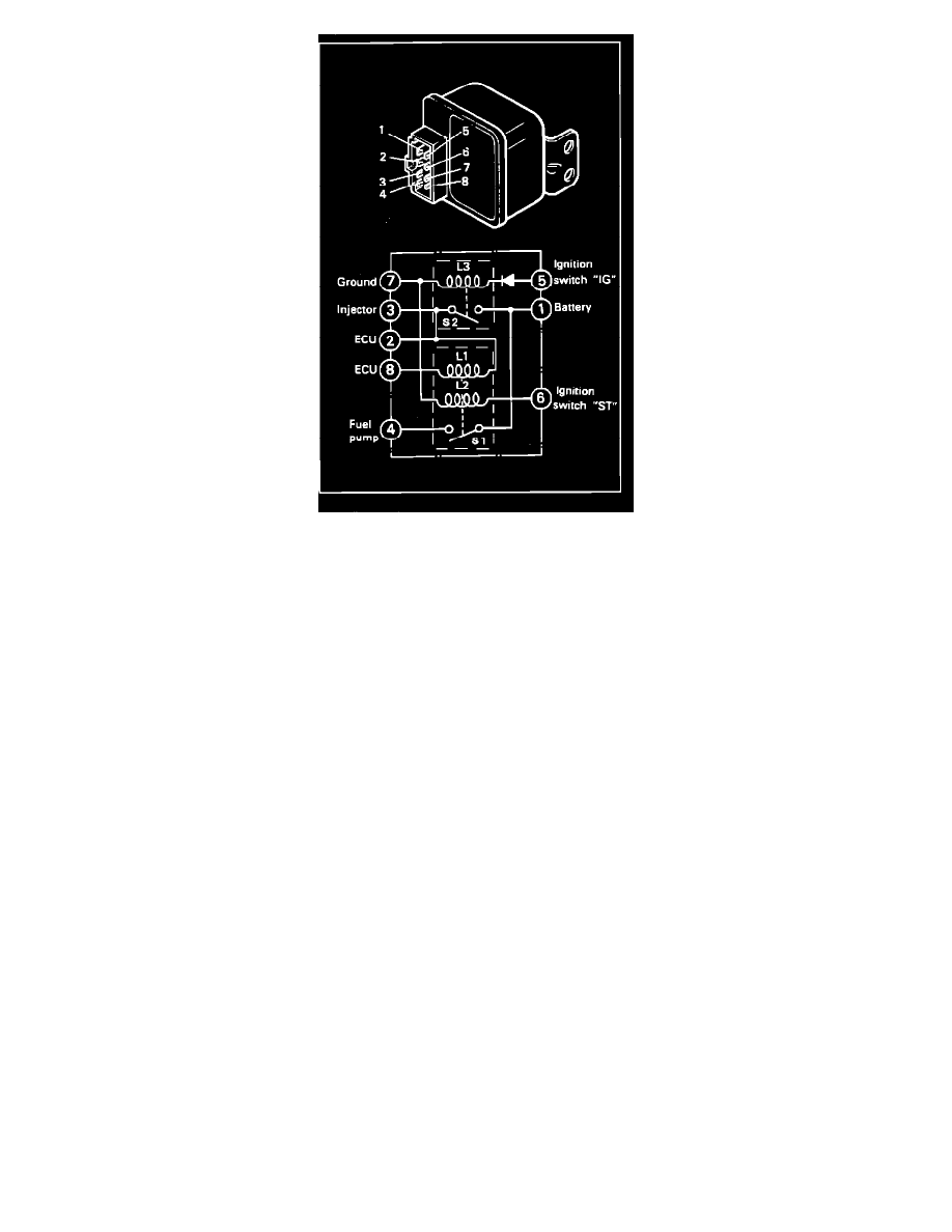
Operation
The operation of the fuel pump is controlled by the ECU through the Control Relay. While cranking, current (supplied by the ignition switch
"START" position) flows through coil L2 to close switch S1. As a result, the fuel pump is energized. Additionally, current (supplied by the
ignition switch "ON" position) flows through coil L3 to close switch S2. As a result, current is supplied to ECU, Air Flow Sensor (AFS), injectors,
EGR solenoid, Purge Control solenoid and the L1 coil of the S1 switch.
After the engine starts and the key is returned to the "ON" position, the ECU provides ground to the L1 coil, allowing the battery current to close
switch S1. As a result the fuel pump continues to be supplied power, but is now under control of the ECU.
In the event of engine stall or other abnormal conditions, the ECU interrupts the ground, opening the L1 coil and interrupting the fuel pump power
circuit.
Note: Failure of the control relay may interrupt power supply to the fuel pump, injectors and/or the ECU, resulting in start failure.