
Laser FWD L4-1997cc 2.0L DOHC (1992)
MAKE SURE ALL TIMING MARKS ARE PROPERLY ALIGNED.
B9. Remove the screwdriver from the balance shaft hole and install the plug. Remove the two clips holding the belt to the camshaft sprockets.
B10. Rotate the crankshaft a 1/4 turn counterclockwise, then rotate it clockwise until the timing marks are aligned again. Crankshaft position should still
be at the No. 1 piston TDC position of the compression stroke.
NOTE:
MAKE SURE ALL TIMING MARKS ARE PROPERLY ALIGNED.
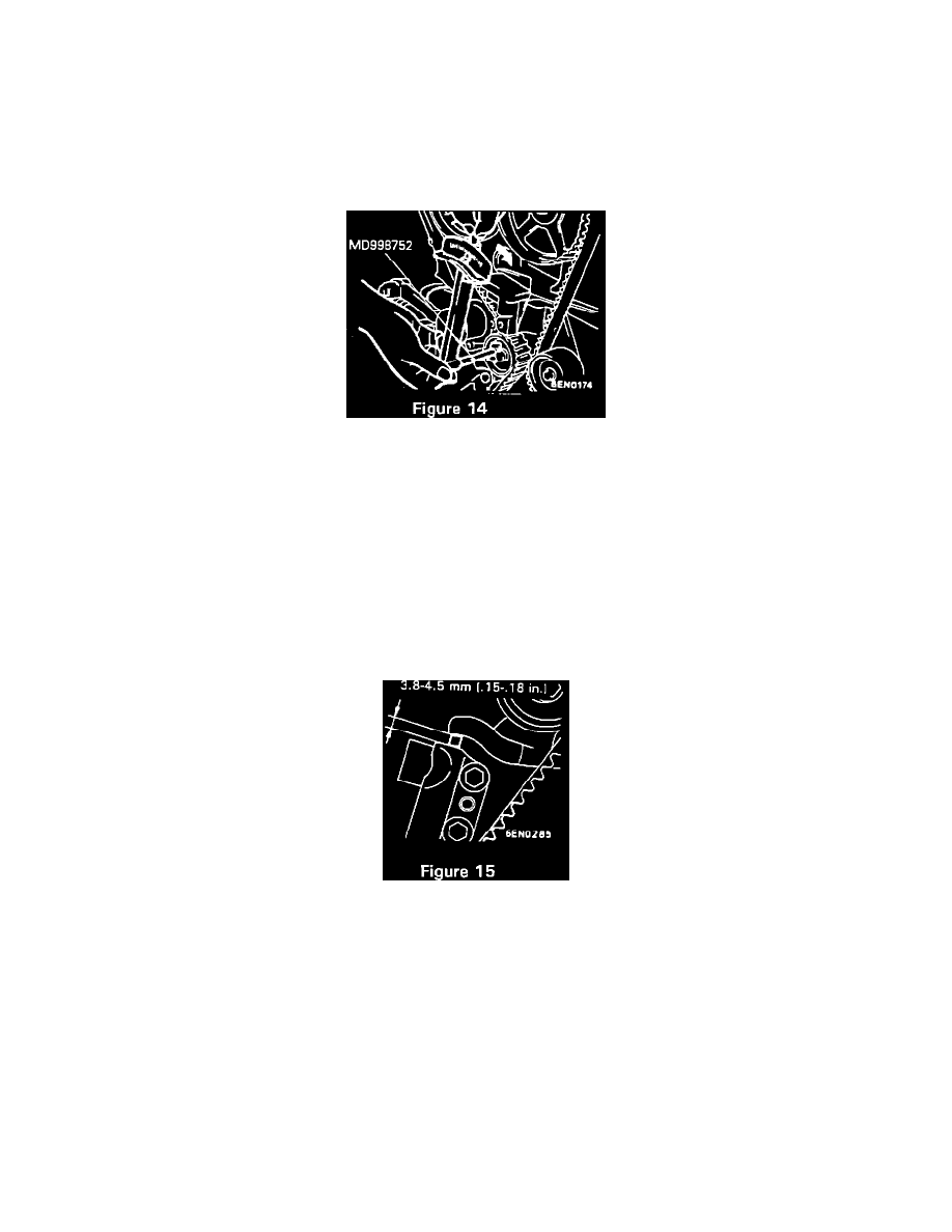
B11. Loosen the tensioner pulley center bolt, attach special tool no. MD998752 (or MD998767) and apply 2.7 N-m (24 in.lbs.) torque to pulley (with
beam type torque wrench) as shown in Figure 14. WITH TORQUE APPLIED TO THE TENSIONER PULLEY, tighten the attaching bolt, then
torque to 49 +/- 6 N-m (36 +/- 4 ft.lbs.).
Caution:
Failure to follow this procedure will cause the belt tension to exceed the range of the auto tensioner limits and result in premature timing belt
failure or jumping.
Note:
If the vehicle body interferes with the special tool and the torque wrench, raise the engine up slightly until there is adequate clearance.
B12. SLOWLY rotate the special tool no. MD998738 until it makes contact with the tensioner arm and remove the alien wrench from the auto
tensioner.
B13. Back off special tool and rotate the crankshaft SIX complete turns clockwise. Measure the auto tensioner push rod position with a drill bit
(distance between the tensioner arm and auto tensioner body) to ensure that it falls within the specification of 3.8-4.5 mm (.15-.18 in.) as shown in
Figure 15.
Note:
Wait 15 minutes after the alien wrench is removed from auto tensioner and crankshaft has been rotated (for plunger rod to stabilize) before
measuring. If the plunger rod is out of specification, reset the auto tensioner (steps A10 & A11) and repeat steps B11 through B13 until the
specified value is obtained.
B14. Remove special tool no. MD998738 and install the rubber plug to the inner timing belt cover.