
Laser FWD L4-1997cc 2.0L DOHC (1992)
32.
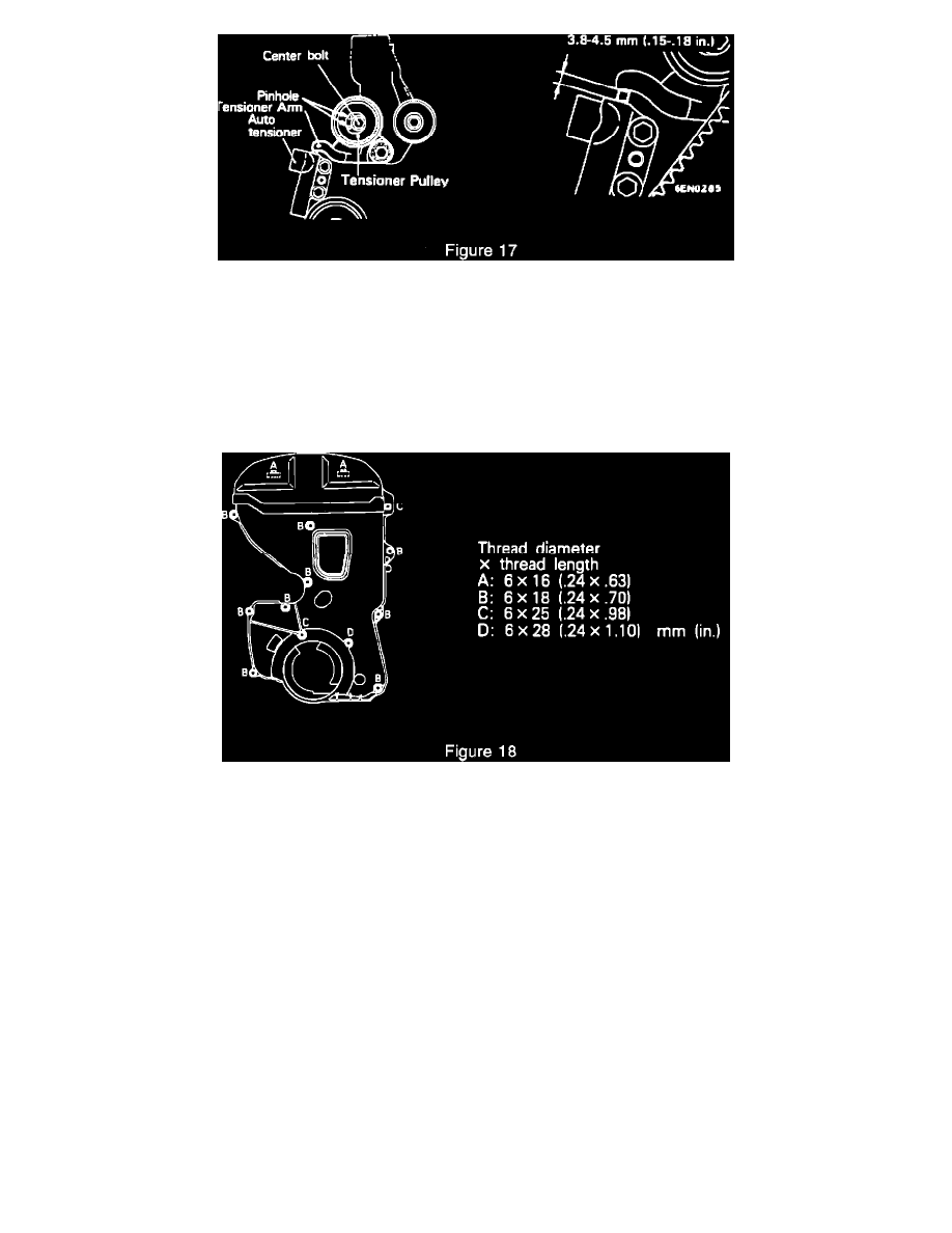
Measure the auto tensioner push rod position with a drill bit (distance between the tensioner arm and auto tensioner body) to ensure that it falls
within the specification of 3.8-4.5 mm (.15-.18 in.) as shown in Fig. 17.
NOTE:
WAIT 15 MINUTES AFTER THE ALLEN WRENCH IS REMOVED FROM AUTO TENSIONER (FOR PLUNGER ROD TO STABILIZE)
BEFORE MEASURING. IF THE PLUNGER ROD IS OUT OF SPECIFICATION, RESET THE AUTO TENSIONER (STEPS 10, 11 AND 12)
AND REPEAT STEPS 29 THROUGH 32 UNTIL THE SPECIFIED VALUE IS OBTAINED.
33.
Remove special tool no. MD998738 and install the rubber plug to the inner timing belt cover.
34.
Install the upper and lower timing belt covers as shown in Fig. 18. (Rotate the bottom of the lower cover toward the rear to assist in clearing the
water pump).
NOTE:
THE TIMING COVER BOLTS VARY IN LENGTH. MAKE SURE THAT THE PROPER SIZE BOLTS ARE INSTALLED IN THE CORRECT
HOLE LOCATIONS Fig. 18.
35.
Install crankshaft pulley and torque to 25 +/- 5 Nm (18 +/- 4 ft.lbs.).
36.
Install A/C tensioner bracket with A/C belt and torque to 25 +/- 2 Nm (18-4 ft.lbs.) Adjust belt tension to 5.5-6.0 mm (.220-.240 in.) belt
deflection.
37.
Install water pump pulley.
38.
Install alternator/water pump and power steering drive belts and adjust belt tension as follows:
Belt Deflection
Alternator/Water Pump Belt
9.0-11.5 mm (.354-.453 in.)
Power Steering Belt
6.0-9.0 mm (.240-.354 in.)