
Laser FWD L4-1997cc 2.0L DOHC (1992)
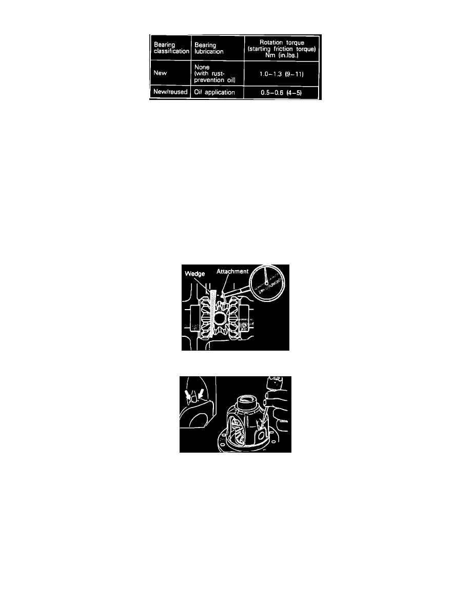
Fig. 44 Checking Drive Pinion Turning Torque
Fig. 45 Drive Pinion Turning Torque Specifications (W/Oil Seal Installed)
4. Adjust drive pinion preload as follows:
a. Fit drive pinion front shims between drive pinion spacer and drive pinion front bearing inner race.
b. Torque companion flange to 116-159 lb-ft using end yoke holder tool No. MB990767 or equivalent.
NOTE: Do not install oil seal.
c. Using a torque wrench, measure drive pinion turning torque as shown.
d. On Colt Vista models, specification is 6-9 lb-in, and on Colt Wagon and Eagle Talon, refer to applicable information. If turning torque is
not within specification, adjust by replacing drive pinion front shims or drive pinion spacer.
NOTE: If a number of shims will be required to bring preload within specified value, reduce the number of shims by replacing the spacer.
e. Remove companion flange and drive pinion, then drive oil seal into gear carrier front lip. Apply a thin coat of multipurpose grease to the oil
seal lip.
f.
Apply a thin coat of multipurpose grease to companion flange washer contacting surface prior to installing drive pinion.
g. Install drive pinion assembly and companion flange with mating marks aligned, and torque companion flange self-locking nut to 116-159 lb-ft.
h. Measure drive pinion turning torque, and compare with specifications. On Colt Vista models, specification is 6-9 lb-in, and on Colt Wagon
and Eagle Talon, refer to appropriate information. If turning torque is not within specified range, ensure companion flange self-locking nut is
tightened to specification and oil seal is correctly installed.
Fig. 46 Checking Differential Gear Backlash
Fig. 47 Lockpin Installation
5. On except 1992 Laser and Talon models, adjust differential gear backlash as follows:
a. Assemble side gears, side gear spacers, pinion gears and pinion washers into differential case.
b. Temporarily install pinion shaft.
NOTE: Do not drive in lockpin at this time.
c. While locking side gear with wedge, measure differential gear backlash with dial indicator as shown. Measurement should be made for both
gears individually.
d. Gear backlash should not exceed 0.008 inch (.2 mm). If side gear exceeds limit, adjust by installing thicker side gear spacers.
e. After adjustment, ensure differential gear rotates smoothly.
f.
If backlash cannot be adjusted within specified range, replace side gear and pinion gear as a set.
g. Align pinion shaft lockpin hole with differential case lockpin hole, and drive in lockpin.
h. Stake lockpin with punch at two points as shown.
6. On all models, clean drive gear attaching bolts, then using a M10 X 1.25 tap, remove adhesive adhering to threaded holes of drive gear. Clean