
Laser FWD L4-1997cc 2.0L DOHC Turbo (1993)
c. Dip valve in engine oil heated to 212°F. Dimension L should now be at least 1.570 inch.
5.
On all models, inspect oil pump as follows:
a. Install oil pump gears in front case and rotate gears, ensuring smooth rotation without excessive looseness.
b. Check for for ridge wear on surface of oil pump cover.
c. Check drive gear and driven gear tip clearance.
d. Check side clearance of gears.
6.
Inspect silent shaft for the following:
a. Clogged oil passages.
b. Seized or damaged journal.
c. Ensure oil clearance is within specifications. Clearance should be as follows: right front, 0.0008 - 0.0024 inch; right rear, 0.0008 - 0.0021 inch;
left front, 0.0002 - 0.0036 inch; left rear, 0.0017 - 0.0033 inch.
7.
Inspect oil jet and check valve for clogging or damage.
ASSEMBLY
Reverse removal procedure to install, noting the following:
1.
When installing oil jet, ensure nozzle is installed toward the piston.
Fig. 39 Installing Left Silent Shaft Rear Bearing.
2.
When installing left silent shaft rear bearing, apply clean engine oil to engine block bearing hole and to outer circumference of bearing. Using
bearing installation tool No. MD998374 or equivalent, install bearing into cylinder block.
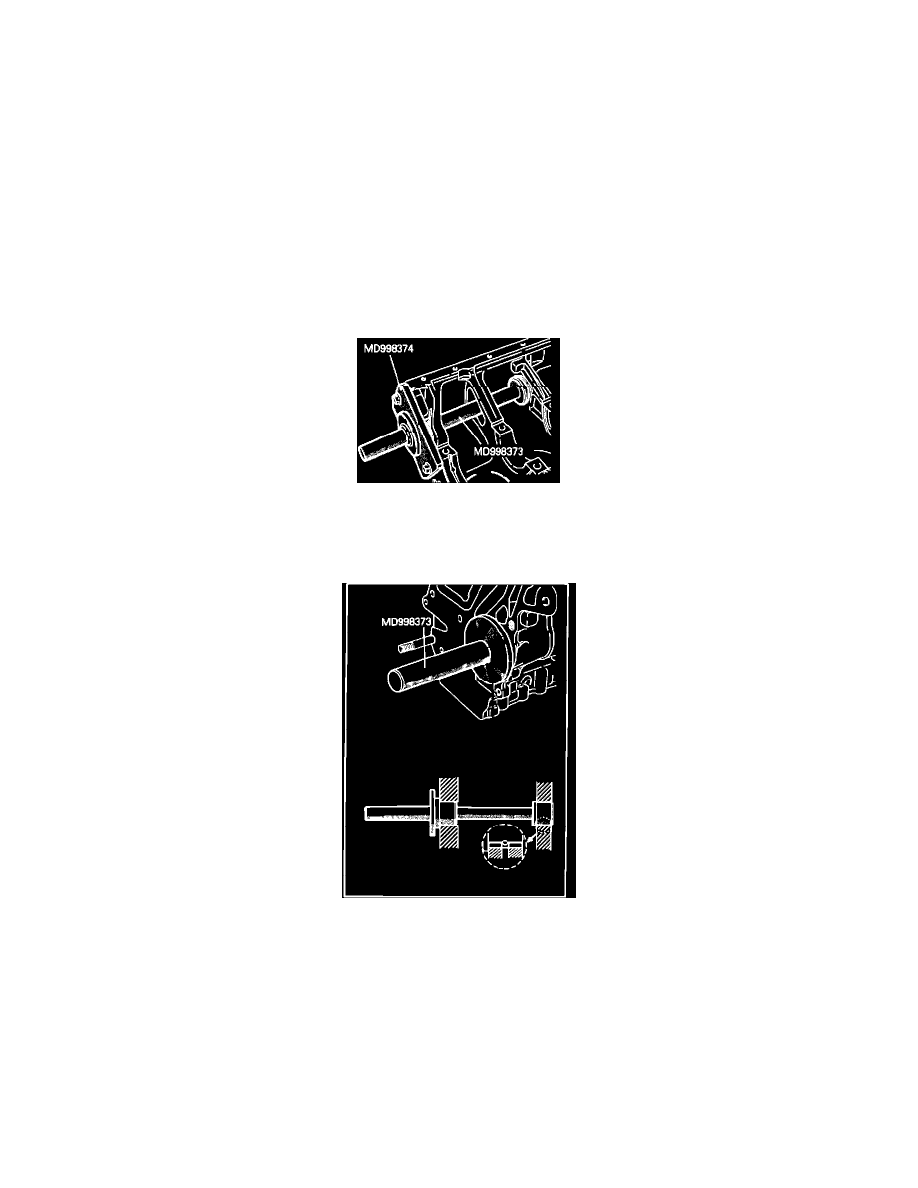
Fig. 40 Installing Right Silent Shaft Rear Bearing.
3.
When installing right silent shaft rear bearing, apply clean engine oil to engine block bearing hole and to outer circumference of bearing. Using
bearing installation tool No. MD998373 or equivalent, install bearing into cylinder block. Ensure oil hole in bearing is aligned with oil hole in
cylinder block.