
Laser FWD L4-1997cc 2.0L DOHC Turbo (1993)
The camshaft sprocket dowel pins must be at the 12 o'clock position and the camshaft sprocket timing marks must be aligned together (left
sprocket at the 3 o'clock and right sprocket at the 9 o'clock positions). Both camshaft sprocket timing marks must be in line with the top surface of
the cylinder head. [A straight edge (ruler) laid across the center of the camshaft attaching bolts will help you to better see and align the timing
marks.] The crankshaft and oil pump sprockets must also be aligned with their respective timing marks.
NOTE:
CRANKSHAFT MAY NEED TO BE ROTATED UP TO SIX TURNS BEFORE ALL SPROCKETS ARE PROPERLY ALIGNED AND THE
REAR BALANCE SHAFT IS IN PHASE, DUE TO THE OIL PUMP - TO BALANCE SHAFT GEAR RATIO.
9.
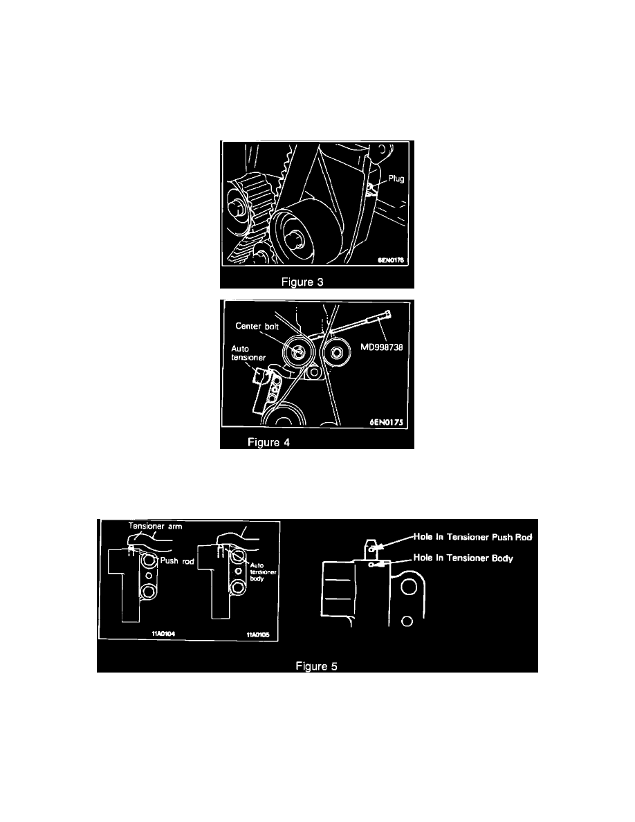
Remove rubber plug from inner timing belt cover and screw special tool no. MD998738 into the engine left support bracket until it makes contact
with the tensioner arm Fig. 3 & 4.
10.
Loosen the tensioner pulley center bolt Fig. 4.
11.
Compress the Auto Tensioner push rod by SLOWLY rotating special tool no. MD998738 until hole in Auto Tensioner push rod aligns with the
hole in the Auto Tensioner body Fig. 5.
NOTE:
PUSH ROD MAY NEED TO BE ROTATED IF HOLE IN ROD IS NOT VERTICALLY IN LINE WITH HOLE IN HOUSING.
12.
Insert a 1/16 inch allen wrench or similar pin (1.4 mm (.055 in.) in diameter) into the aligned holes to hold the push rod in the reset (pinned)
position. Back off special tool MD998738 once auto tensioner is in the reset position Fig. 5.